Ureteral stent tube

A ureteral stent tube and tube wall technology, applied in the direction of catheters, wound drainage devices, guide wires, etc., can solve the problems of long time, great pain, inconvenient extraction, etc., to achieve controllable time, relieve pain, and pull out convenient effect

Pending Publication Date: 2020-06-30
珠海天达生物科技有限公司
View PDF0 Cites 4 Cited by
  • Summary
  • Abstract
  • Description
  • Claims
  • Application Information

AI Technical Summary

Problems solved by technology

The existing ureteral stent needs to be pulled out with the help of a rigid cystos

Method used


Image

  • Ureteral stent tube
  • Ureteral stent tube
  • Ureteral stent tube

Examples


Embodiment 1

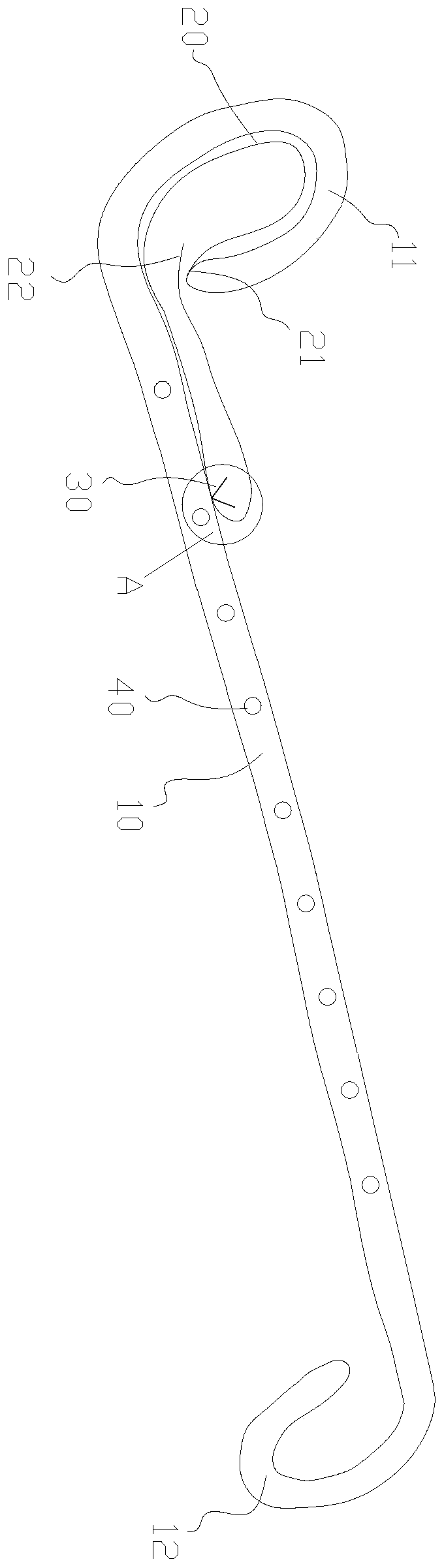
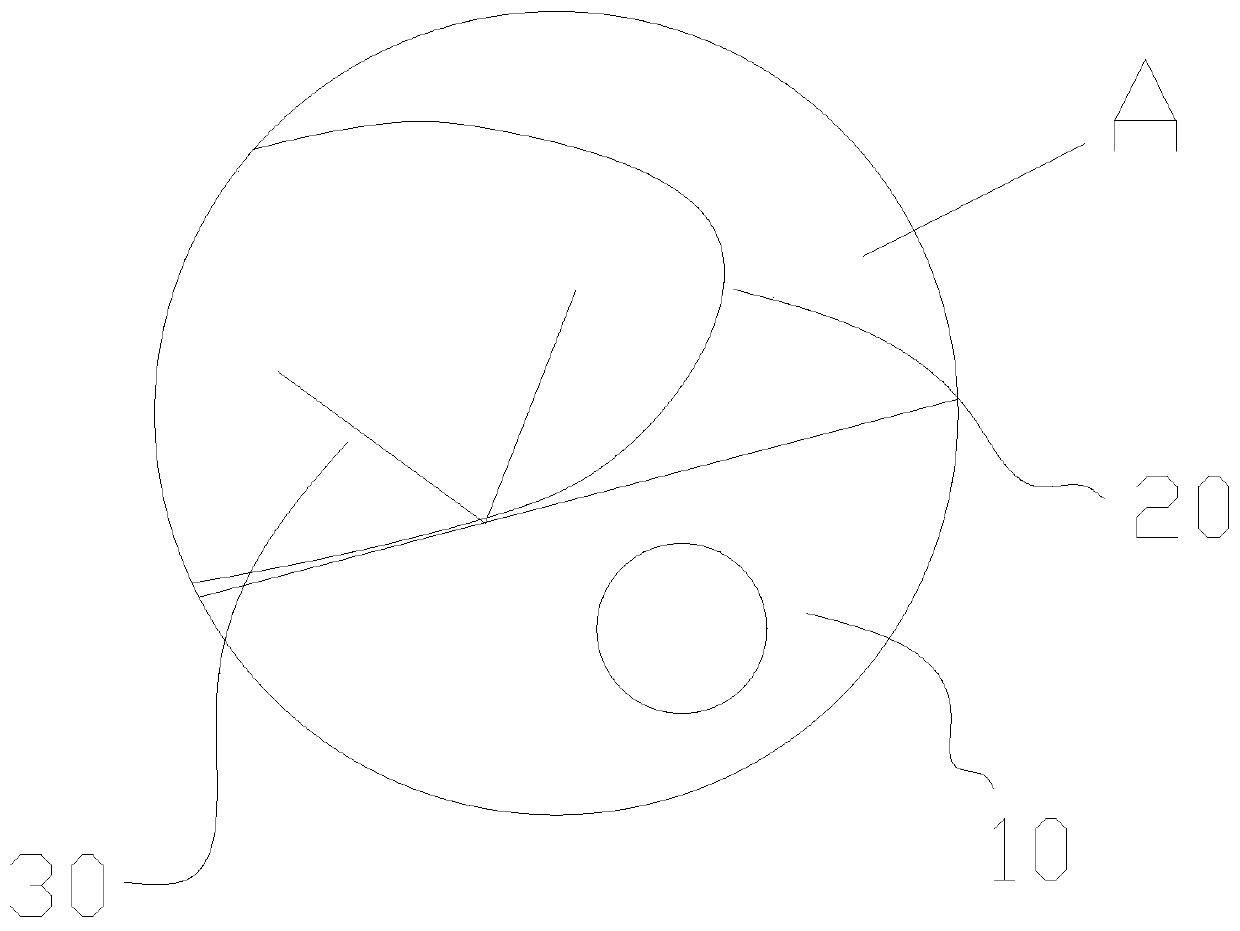
[0023] see figure 1 and figure 2 , the present embodiment provides a ureteral stent, including a tubular body 10 and a pull wire 20, the body 10 is made of medical polymer materials, such as polyethylene, silicone resin, silicone-based block copolymers, etc. The body 10 has a first end 11 and a second end 12 oppositely arranged, the first end 11 of the body 10 is bent into an arc shape, the second end 12 is bent into an arc shape, and the direction of the second end 12 of the body 10 is bent It is opposite to the bending direction of the first end 11 of the body 10; the pulling wire 20 is fixed on the tube wall of the body 10 through a degradable fixing wire 30, one end of the pulling wire 20 is a fixed end 21, and the other end is a free end 22. The fixed end 21 of the wire 20 is fixed to the end of the first end 11 of the body 10 . Several urinary catheterization holes 40 are arranged on the pipe wall of the main body 10 .

[0024] Preferably, the fixed end 21 of the pul...

Embodiment 2

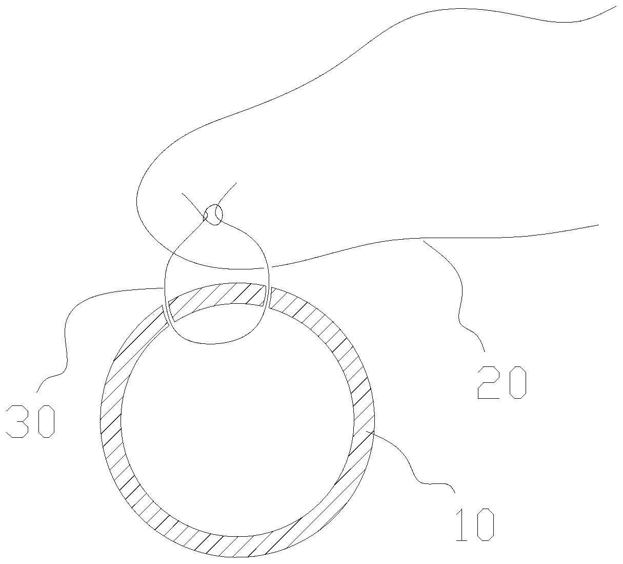
[0032] refer to Figure 4 , the present embodiment provides a ureteral stent, including a tubular body 10 and a pull wire 20, the body 10 is made of medical polymer materials, such as polyethylene, silicone resin, silicone-based block copolymers, etc. The body 10 has a first end 11 and a second end 12 oppositely arranged, the first end 11 of the body 10 is bent into an arc shape, the second end 12 is bent into an arc shape, and the direction of the second end 12 of the body 10 is bent It is opposite to the bending direction of the first end 11 of the body 10; compared with Embodiment 1, the difference is that one end of the pull wire 20 is a fixed end 21, and the other end is a free end 22. On the fixed end 21 of the pull wire 20 Connected with a wire loop 23 , the pulling wire 20 is sewn on the tube wall of the body 10 , and the free end of the pulling wire 20 passes through the wire loop 23 on the fixed end 21 of the pulling wire 20 . refer to Figure 5 , the specific oper...


PUM

PropertyMeasurementUnit
Lengthaaaaaaaaaa
Lengthaaaaaaaaaa
Lengthaaaaaaaaaa

Abstract

The invention provides a ureteral stent tube. The ureteral stent tube comprises a tubular body and a traction line, wherein the body is provided with a first end and a second end which are arranged oppositely; the first end of the body is bent into a circular arc shape, and the second end of the body is bent into a circular arc shape; the bending direction of the second end of the body is oppositeto that of the first end of the body; the traction line is fixed on the tube wall of the body through a degradable fixing line; one end of the traction line is a fixed end, and the other end of the traction line is a free end; and the fixed end of the traction line is fixed with the end part of the first end of the body. Compared with the prior art, the ureteral stent tube provided by the invention has the advantages that: the traction line can be automatically released after the ureteral stent tube is placed into a body for a period of time, and the ureteral stent tube can be pulled out by pulling the traction line in vitro, so that pain of a patient caused by cystoscope operation and injury to the patient during pulling are relieved; and the ureteral stent tube has the advantages of controllable time, convenience for pulling and the like.

Description

technical field [0001] The invention relates to the technical field of medical instruments, in particular to a ureteral stent tube. Background technique [0002] A ureteral stent is a long, thin tube that runs from the kidney to the bladder. When the ureter is blocked, a ureteral stent supports the ureter so that urine can drain from the kidney to the bladder. [0003] Ureteral stents are widely used in urological surgery, and currently there is no ureteral stent that can be permanently placed in the body. Existing ureteral stents need to be pulled out with the help of a rigid cystoscope, which is painful, damaged, and takes a long time, making it inconvenient to pull out. Contents of the invention [0004] The technical problem to be solved by the present invention is to provide a ureteral stent tube with controllable time and convenient extraction. [0005] The present invention provides a ureteral stent tube, comprising a tubular structure body and a pulling wire, th...

Claims


Application Information

Patent Timeline
IPC IPC(8): A61M25/00A61M25/09
CPCA61M25/0082A61M25/09A61M27/008
Inventor 郭振宇
Owner 珠海天达生物科技有限公司
Why Eureka
Try Eureka