Calibration device and calibration method for robot welding torch and laser sensor
A laser sensor and calibration device technology, applied in the direction of using optical devices, measuring devices, instruments, etc., can solve problems such as manual intervention, and achieve the effect of solving manual intervention
- Summary
- Abstract
- Description
- Claims
- Application Information
AI Technical Summary
Problems solved by technology
Method used
Image
Examples
Embodiment 1
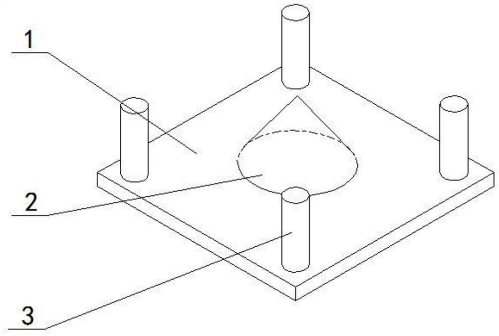
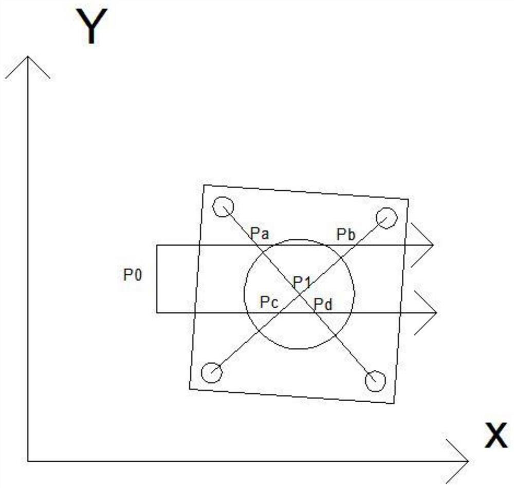
[0023]Embodiment 1, a calibration device for a robot welding torch and a laser sensor, including a base plate 1, on which a cone 2 with a vertical section with a large top and a small structure is installed, and the cone 2 is evenly distributed in the upper direction of the base plate around the cone 2 There are four signal columns 3, on which a photoelectric sensor connected to the robot is installed, the height of the photoelectric sensor is 8-12mm higher than the apex of the cone, and the opposite signal columns are respectively set as emission columns, and are connected with the robot. The transmitting column corresponds to the matching receiving column, and the calibration method is realized by the following steps: (1) Install the laser sensor on the outer end of the welding torch of the welding robot, establish communication between the laser sensor and the welding robot, fix the base plate on the workbench, and coordinate the base plate and the robot The angle between th...
Embodiment 2
[0031] Embodiment 2, in the calibration device and calibration method of the robot welding torch and laser sensor described in Embodiment 1: a base plate is included, and a cone with a longitudinal section with a large upper and a smaller structure is installed on the base plate, and the base plate around the cone There are four signal columns evenly distributed in the circumferential direction, and photoelectric sensors connected to the robot are installed on the signal columns. The height of the photoelectric sensors is 8mm higher than the apex of the cone. The opposing signal columns are respectively set as emission columns, and The receiving column corresponding to the transmitting column, the calibration method is realized by the following steps: (1) Install the laser sensor on the outer end of the welding torch of the welding robot, establish communication between the laser sensor and the welding robot, fix the base plate on the workbench, the base plate and the robot The...
Embodiment 3
[0039] Embodiment 3, in the calibration device and calibration method of the robot welding torch and laser sensor described in embodiment 1 or 2: comprising a base plate, on which a cone with a large upper and a smaller structure is installed in the longitudinal section, and in the cone There are four signal columns evenly distributed in the circumferential direction of the base plate around. On the signal columns, photoelectric sensors connected to the robot are installed. The height of the photoelectric sensors is 12mm higher than the apex of the cone. The opposing signal columns are respectively set as emission columns. , and the receiving column corresponding to the transmitting column, the calibration method is realized by the following steps: (1) Install the laser sensor on the outer end of the welding torch of the welding robot, establish communication between the laser sensor and the welding robot, fix the base plate on the workbench, the base plate The included angle w...
PUM
| Property | Measurement | Unit |
|---|---|---|
| angle | aaaaa | aaaaa |
Abstract
Description
Claims
Application Information
 - R&D
- Intellectual Property
- Life Sciences
- Materials
- Tech Scout
- Unparalleled Data Quality
- Higher Quality Content
- 60% Fewer Hallucinations
Browse by: Latest US Patents, China's latest patents, Technical Efficacy Thesaurus, Application Domain, Technology Topic, Popular Technical Reports.
© 2025 PatSnap. All rights reserved.Legal|Privacy policy|Modern Slavery Act Transparency Statement|Sitemap|About US| Contact US: help@patsnap.com


