Movable lifting wet cutting machine

A cutting machine, lifting mechanism technology, applied in grinding machines, metal processing equipment, grinding/polishing equipment, etc., can solve the problems of environmental pollution, heavy hand-held parts of cutting machines, inconvenient for carving, grinding and cutting, etc.

Pending Publication Date: 2020-06-30
QUYANG ZHONGYOU AUTOMATION EQUIP CO LTD
View PDF0 Cites 0 Cited by
  • Summary
  • Abstract
  • Description
  • Claims
  • Application Information

AI Technical Summary

Problems solved by technology

The engraving of traditional stone has also changed from manual engraving to electric engraving. This progress has greatly improved the efficiency of engraving, but the electric cutting machine in the electric engraving equipment will generate a lot of flying dust when it is working, which has caused serious damage to the environment. A large amount of pollution. Based on this, the above problems can be solved by spraying water on the grinding parts for wet grinding during the grinding process. However, since the conventional cutting machine adopts a transmission mode that is directly connected to the gear by the motor, water is used during wet grinding. It is unavoidable to touch the motor and cause leakage
[0003] Because the existing cutting machine integrates the power unit and the cutting disc, the hand-held part of the cutting machine is too heavy, which is inconvenient for engraving, grinding and cutting.

Method used


Image

  • Movable lifting wet cutting machine
  • Movable lifting wet cutting machine

Examples


Embodiment Construction

[0016] The present invention will be further described below in conjunction with the accompanying drawings. It should be noted that this embodiment is based on the technical solution, and provides detailed implementation and specific operation process, but the protection scope of the present invention is not limited to the present invention. Example.

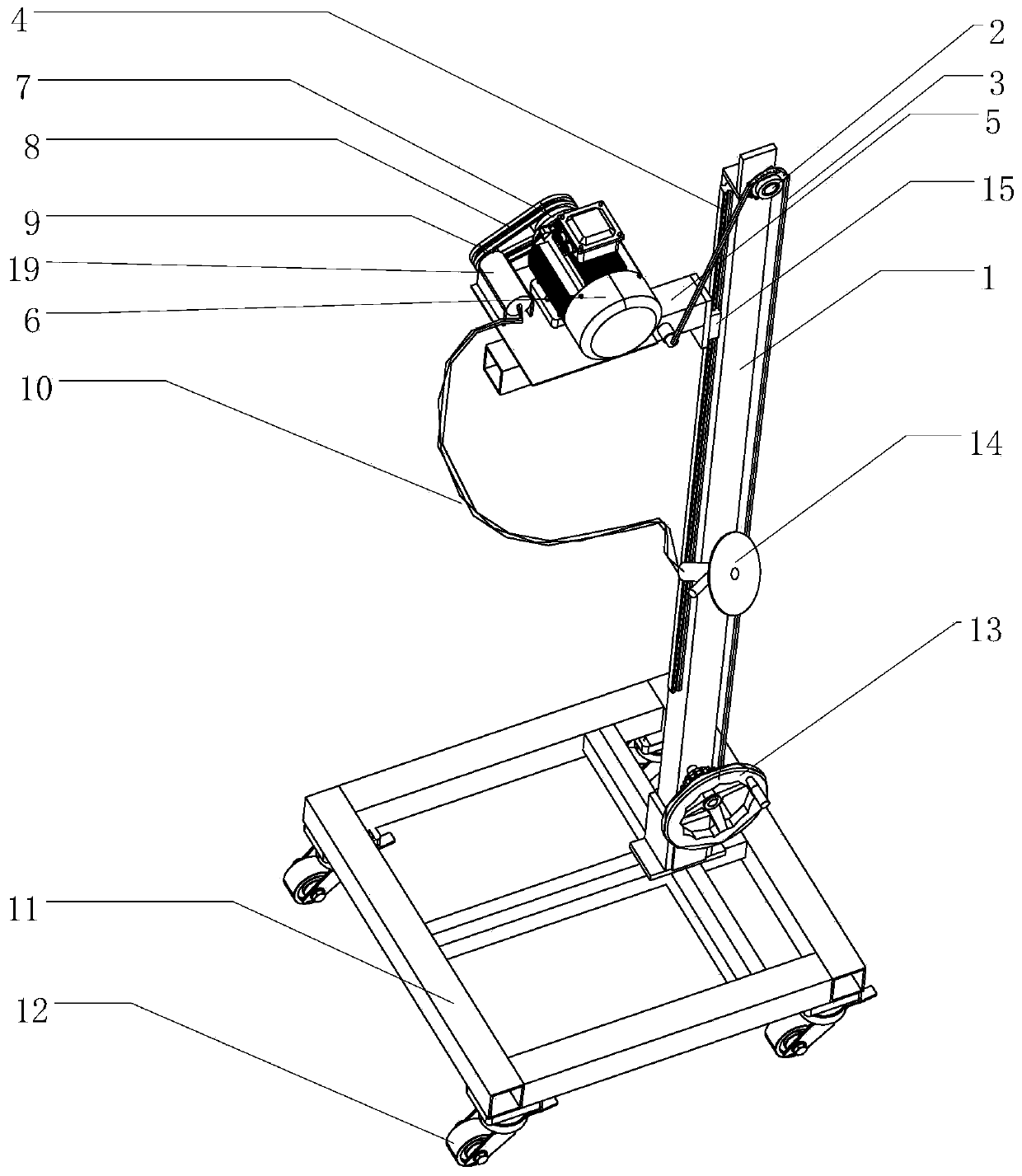
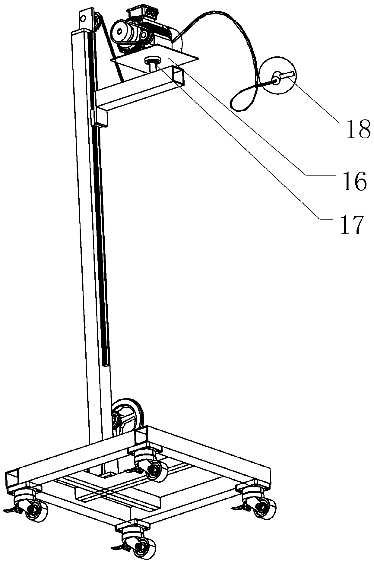
[0017] figure 1 It is a structural schematic diagram of a viewing angle of a movable lifting wet cutting machine of the present invention, figure 2 It is a structural schematic diagram of a perspective of a movable lifting wet cutting machine of the present invention, as figure 1 and figure 2 As shown, the structure of the present invention is a movable lifting wet cutting machine, including: a base 11, a lifting mechanism arranged on the top of the base 11, and a power unit for generating a power source that is slidably connected to the lifting mechanism, The power unit includes a motor 6 and a motor platform 16 for carryi...


PUM


Abstract

The invention discloses a movable lifting wet cutting machine. The movable lifting wet cutting machine comprises a base, a lifting mechanism arranged at the top end of the base and a power unit connected to the lifting mechanism in a sliding mode and used for generating a power source, the power output end of the power unit is connected with a steel wire flexible shaft device used for transmittingpower, and the end, away from the power unit, of the steel wire flexible shaft device is connected with a cutting mechanism. By the adoption of the structure, the movable lifting wet cutting machineeffectively prevents a large amount of flying dust from being generated, the overall structure is simple, the handheld part is light and easy to operate, and the production efficiency of operators isgreatly improved.

Description

technical field [0001] The invention relates to a sculpture technology, in particular to a movable lifting wet cutting machine. Background technique [0002] At present, the production of sculptures has been mechanized and automated, and the production process has been gradually improved. The engraving of traditional stone has also changed from manual engraving to electric engraving. This progress has greatly improved the efficiency of engraving, but the electric cutting machine in the electric engraving equipment will generate a lot of flying dust when it is working, which has caused serious damage to the environment. A large amount of pollution. Based on this, the above problems can be solved by spraying water on the grinding parts for wet grinding during the grinding process. However, since the conventional cutting machine adopts a transmission mode that is directly connected to the gear by the motor, water is used during wet grinding. It is unavoidable to touch the moto...

Claims


Application Information

Patent Timeline
Patent Type & Authority Applications(China)
IPC IPC(8): B24B27/08B24B55/00
CPCB24B27/08B24B27/085B24B55/00
Inventor 张玉强郑成林张冲李海伟
Owner QUYANG ZHONGYOU AUTOMATION EQUIP CO LTD
Why Eureka
Try Eureka