High-voltage pulsed electric field-cyclone centrifugal field combined lubricating oil demulsification and dehydration device

A technology of high-voltage pulse electric field and high-voltage pulse power supply, which is applied in the direction of electric/magnetic dehydration/demulsification, lubricating composition, mechanical dehydration/demulsification, etc., which can solve the problems of poor treatment effect, high energy consumption, and long time consumption, etc. problem, to achieve the effect of short time-consuming, low energy consumption and good processing effect

Active Publication Date: 2020-06-30
CHONGQING TECH & BUSINESS UNIV
View PDF11 Cites 1 Cited by
  • Summary
  • Abstract
  • Description
  • Claims
  • Application Information

AI Technical Summary

Problems solved by technology

[0005] The purpose of the present invention is to propose a high-voltage pulse electric field-swirl centrifuge for the problems of long time consumption, high energy consumption, and poor treatment effect in the demulsification and dehydration of high-water lubricating oil in traditional processes such as vacuum heating and separation. Field joint lubricating oil demulsification and dehydration device, high-voltage pulse electric field is used to complete the rapid coalescence of emulsified droplets in lubricating oil and the settlement of large droplets, and the swirl centrifugal field is used to quickly remove medium and small droplets in lubricating oil. The effective synergy between the high-voltage pulsed electric field and the swirling centrifugal field improves the demulsification and dehydration efficiency and realizes the rapid and efficient demulsification and dehydration of lubricating oil

Method used


Image

  • High-voltage pulsed electric field-cyclone centrifugal field combined lubricating oil demulsification and dehydration device
  • High-voltage pulsed electric field-cyclone centrifugal field combined lubricating oil demulsification and dehydration device
  • High-voltage pulsed electric field-cyclone centrifugal field combined lubricating oil demulsification and dehydration device

Examples


no. 1 example

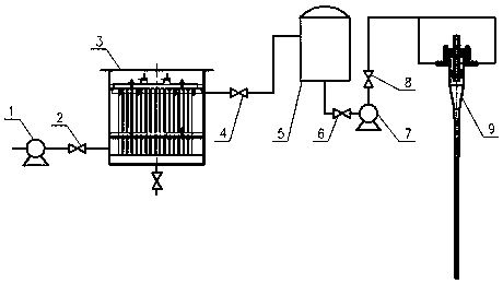
[0044] 1) A high-voltage pulse electric field-swirl centrifugal field combined lubricating oil demulsification and dehydration device, including an oil inlet pump 1 (1), an oil delivery valve 1 (2), a high-voltage pulse electric field demulsification and dehydration device (3), and an oil delivery valve 2(4), buffer oil storage tank (5), oil delivery valve 3(6), oil inlet pump 2(7), oil delivery valve 3(8), cyclone centrifugal demulsification and dehydration device (9), characterized in that : The oil inlet pump 1 (1) is connected to the lubricating oil that needs to be demulsified and dehydrated through the oil pipeline, and then through the oil pipeline and the oil delivery valve 1 (2), the high-voltage pulse electric field demulsification and dehydration device (3), and the oil delivery valve 2 (4), buffer oil storage tank (5), oil delivery valve 3 (6), oil inlet pump 2 (7), oil delivery valve 3 (8) and cyclone centrifugal demulsification dehydration device (9) link to each ...

no. 2 example

[0055] 1) A high-voltage pulse electric field-swirl centrifugal field combined lubricating oil demulsification and dehydration device, including an oil inlet pump 1 (1), an oil delivery valve 1 (2), a high-voltage pulse electric field demulsification and dehydration device (3), and an oil delivery valve 2(4), buffer oil storage tank (5), oil delivery valve 3(6), oil inlet pump 2(7), oil delivery valve 3(8), cyclone centrifugal demulsification and dehydration device (9), characterized in that : The oil inlet pump 1 (1) is connected to the lubricating oil that needs to be demulsified and dehydrated through the oil pipeline, and then through the oil pipeline and the oil delivery valve 1 (2), the high-voltage pulse electric field demulsification and dehydration device (3), and the oil delivery valve 2 (4), buffer oil storage tank (5), oil delivery valve 3 (6), oil inlet pump 2 (7), oil delivery valve 3 (8) and cyclone centrifugal demulsification dehydration device (9) link to each ...

no. 3 example

[0066] 1) A high-voltage pulse electric field-swirl centrifugal field combined lubricating oil demulsification and dehydration device, including an oil inlet pump 1 (1), an oil delivery valve 1 (2), a high-voltage pulse electric field demulsification and dehydration device (3), and an oil delivery valve 2(4), buffer oil storage tank (5), oil delivery valve 3(6), oil inlet pump 2(7), oil delivery valve 3(8), cyclone centrifugal demulsification and dehydration device (9), characterized in that : The oil inlet pump 1 (1) is connected to the lubricating oil that needs to be demulsified and dehydrated through the oil pipeline, and then through the oil pipeline and the oil delivery valve 1 (2), the high-voltage pulse electric field demulsification and dehydration device (3), and the oil delivery valve 2 (4), buffer oil storage tank (5), oil delivery valve 3 (6), oil inlet pump 2 (7), oil delivery valve 3 (8) and cyclone centrifugal demulsification dehydration device (9) link to each ...


PUM

PropertyMeasurementUnit
strengthaaaaaaaaaa
strengthaaaaaaaaaa
strengthaaaaaaaaaa

Abstract

The invention discloses a high-voltage pulsed electric field-cyclone centrifugal field combined lubricating oil demulsification and dehydration device comprising an oil inlet pump 1 (1), an oil delivery valve 1 (2), a high-voltage pulsed electric field demulsification and dehydration device (3), an oil delivery valve 2 (4), a buffer oil storage tank (5), an oil delivery valve 3 (6), an oil inlet pump 2 (7), an oil delivery valve 3 (8) and a cyclone centrifugal demulsification and dehydration device (9); the device is characterized in that the oil inlet pump 1 (1) is connected with lubricatingoil needing demulsification and dehydration treatment through an oil pipeline, and then is connected with the oil delivery valve 1 (2), the high-voltage pulsed electric field demulsification and dehydration device (3), the oil delivery valve 2 (4), the buffer oil storage tank (5), the oil delivery valve 3 (6), the oil inlet pump 2 (7), the oil delivery valve 3 (8) and the cyclone centrifugal demulsification and dehydration device (9) through oil pipelines. The demulsification and dehydration efficiency can be improved, rapid and efficient demulsification and dehydration of high-water-content lubricating oil is achieved, and the technology and economic advantages are obvious.

Description

technical field [0001] This patent belongs to the technical field of demulsification and dehydration of lubricating oil, and is a device for demulsification and dehydration of lubricating oil by combining a high-voltage pulse electric field and a swirl centrifugal field. Background technique [0002] Lubricating oil mainly plays the role of lubrication, heat dissipation and shock absorption in equipment. As the second largest petroleum product after fuel oil, it is widely used in equipment transmission systems in the fields of automobiles, petrochemicals, metallurgy, and electric power. The dehydration and purification treatment of lubricating oil plays an important role in prolonging the service life of oil products, recycling oil products, reducing the generation of waste oil and ensuring the safety of equipment operation. [0003] With the rapid development of metallurgy, chemical industry, automobile and other basic industries in our country, the amount of lubricating oi...

Claims


Application Information

Patent Timeline
Patent Type & Authority Applications(China)
IPC IPC(8): C10G33/02C10G33/06C10M175/00
CPCC10G33/02C10G33/06C10M175/00C10G2300/201C10G2400/10
Inventor 陈凌龚海峰张贤明邱值
Owner CHONGQING TECH & BUSINESS UNIV
Why Eureka
Try Eureka