Electromagnetic actuating device

A manipulation device, electromagnetic technology, applied in the direction of electromagnet, valve device, valve operation/release device, etc., to achieve the effect of improving stability or shape stability and reducing risk

Active Publication Date: 2020-06-30
ROBERT BOSCH GMBH
View PDF7 Cites 0 Cited by
  • Summary
  • Abstract
  • Description
  • Claims
  • Application Information

AI Technical Summary

Problems solved by technology

However, the embodiment of the magnetic separation mechanism is associated with a certain amount of effort in production

Method used


Image

  • Electromagnetic actuating device
  • Electromagnetic actuating device
  • Electromagnetic actuating device

Examples


Embodiment Construction

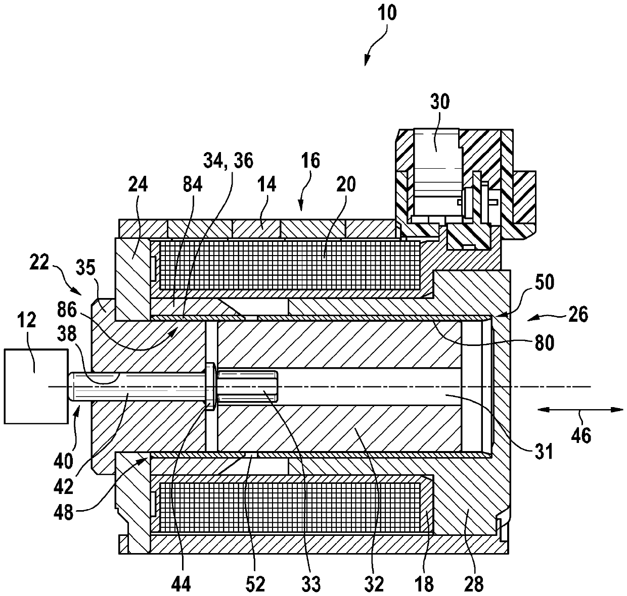
[0027] Electromagnetic control device in figure 1The center bears the reference numeral 10 as a whole. Such electromagnetic actuating devices 10 are used, for example, in the transmission technology of motor vehicles, in particular for controlling clutches of automatic transmissions. For this purpose, hydraulic valves, for example, are actuated via electromagnetic actuating device 10, said hydraulic valves being figure 1 is delineated only schematically by a box provided with the reference numeral 12 .

[0028] The electromagnetic actuating device 10 has a housing 14 in which the components of the electromagnetic actuating device 10 are arranged. The electromagnetic actuating device 10 has a solenoid coil 16 with a coil body 18 and a winding 20 . At the first end side 22 the housing 14 is closed by means of a closure 24 which can be a flux disk. At the second end side 26 , the housing 14 is closed by means of a cover 28 , which can be a magnet core 28 which has a section e...


PUM


Abstract

An electromagnetic actuating device (10) comprises a generally substantially cylindrical pole tube (34), an armature (32) arranged radially inside the pole tube (34), and an electromagnetic coil (16)arranged radially outside the pole tube (34), wherein the pole tube (34) has a first axial end (48) and a second axial end (50). According to the invention, the pole tube (34) is designed as a punchedsleeve (36) having the shape thereof by deformation, said sleeve (36) having perforations (52) extending in the circumferential direction in the vicinity of the first axial end (48).

Description

technical field [0001] The invention relates to an electromagnetic actuation device according to the preamble of claim 1 . Background technique [0002] In automatic passenger car transmissions, hydraulically actuated clutches are used for shifting gears, the hydraulic pressure on the clutch being regulated via a hydraulic slide valve. The slide valve can be actuated via a pilot valve (pilot ventil; pilot control) or directly via a solenoid actuation. In such actuating devices, the embodiment with a pole tube has proven itself in practice, ie the magnet armature is guided in the pole tube. An important development focus was to achieve the highest possible magnetic force level (high lift work), ie the magnetic efficiency had to be set at a high level. Such an actuating device with a pole tube is known from DE 10 2012 223 430 A1, in which the pole tube has a "magnetic separation mechanism" designed as a thin-turned region. The thin-turned region already saturates at low mag...

Claims


Application Information

Patent Timeline
Patent Type & Authority Applications(China)
IPC IPC(8): F16H61/28F16H61/02
CPCF16H61/28F16H61/0202F16K31/0675H01F7/1607H01F7/081H01F2007/083H01F7/16F16D27/00F16D25/12H01F7/129
Inventor K.舒特T.霍夫曼
Owner ROBERT BOSCH GMBH
Why Eureka
Try Eureka