
Method and device for measuring laser far-field divergence angle

A far-field divergence angle and laser technology, which is applied in the direction of measuring devices, testing optical performance, geometric characteristics/aberration measurement, etc., can solve the problems of slow measurement speed and low measurement stability, so as to simplify the test plan and improve the test performance. The effect of speed and test stability

Inactive Publication Date: 2020-06-30
SUZHOU JUZHEN PHOTOELECTRIC
View PDF4 Cites 0 Cited by
  • Summary
  • Abstract
  • Description
  • Claims
  • Application Information

AI Technical Summary

Problems solved by technology

[0003] At present, the conventional detection method on the market is to first fix the laser, and then use the detector to detect the light intensity in the measurement plane parallel to the junction plane and perpendicular to the junction plane to obtain the far-field divergence angle of the laser light source. The method needs to be measured on two planes separately, and two mutually perpendicular measurement planes need to be set, resulting in reduced measurement stability and slower measurement speed

Method used


Image

  • Method and device for measuring laser far-field divergence angle
  • Method and device for measuring laser far-field divergence angle
  • Method and device for measuring laser far-field divergence angle

Examples


Embodiment Construction

[0018] The present invention will be described in detail below in conjunction with the accompanying drawings.

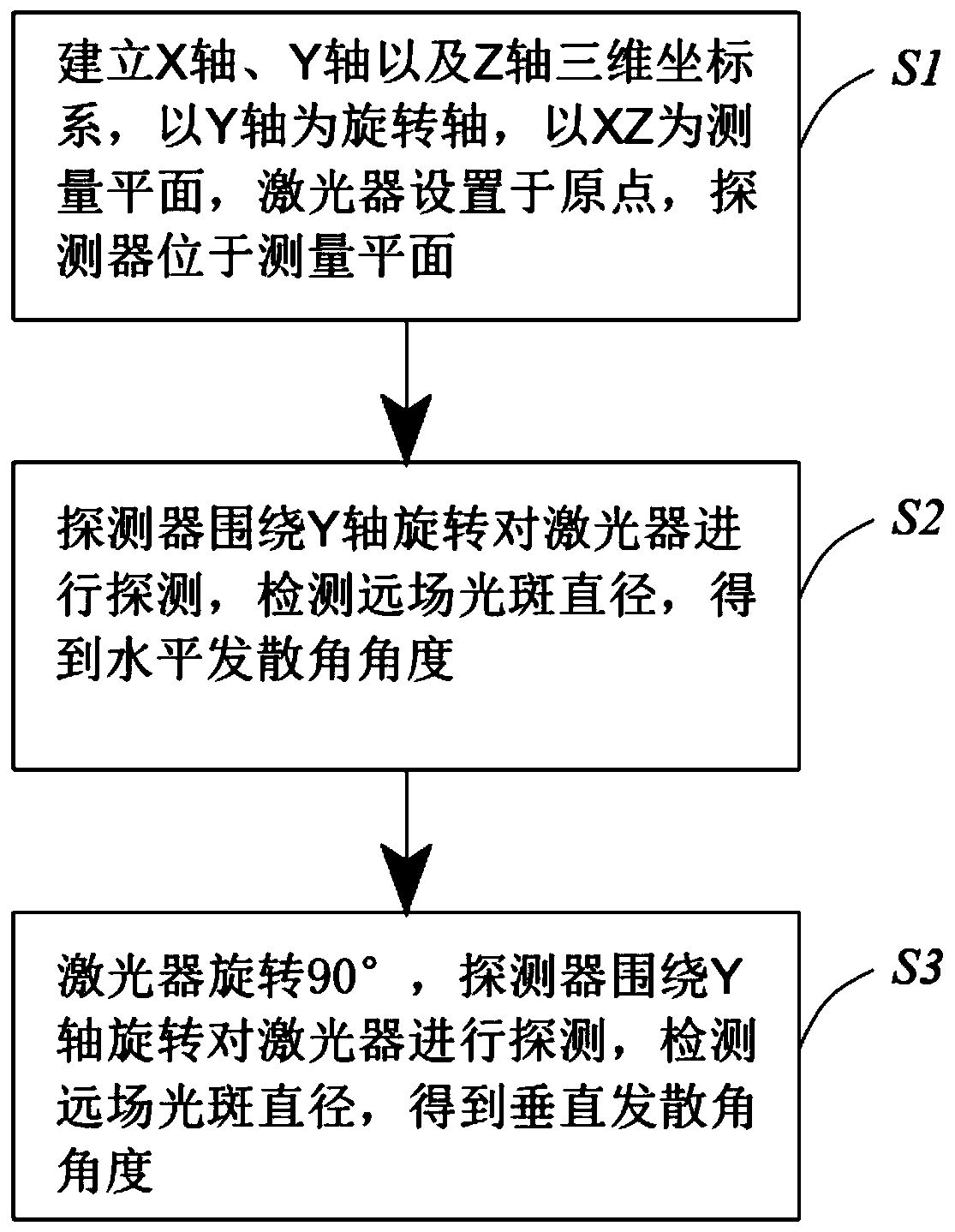
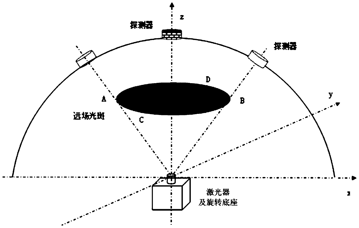
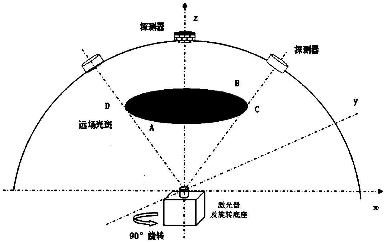
[0019] Such as Figure 1 ~ Figure 3 A method for measuring the far-field divergence angle of a laser is shown, and the operation steps of the method are as follows:

[0020] S1. Determine the X-axis, Y-axis, and Z-axis in three-dimensional space, form a measurement plane with the X-axis and Z-axis, set the laser at the origin of the measurement plane, set the detector in the measurement plane and make the photosensitive surface of the detector face The light-emitting surface of the laser, the detector detects the light emitted by the laser in the measurement plane; when the detector is placed and fixed, it needs to distinguish the position of the junction plane of the laser. By judging the position of the junction plane, the vertical divergence angle and the horizontal divergence angle can be directly obtained. Position: According to the actual situation, the juncti...


PUM

PropertyMeasurementUnit
Radiusaaaaaaaaaa

Abstract

The invention relates to a method and device for measuring a far-field divergence angle of a laser, and the method comprises the steps: S1, an X axis, a Y axis and a Z axis are determined, a measurement plane is formed through X and Z, the laser is set at an original point of the measurement plane, and a light-sensitive surface of a detector faces a light-emitting surface of the laser; S2, the detector rotates around the Y axis, the light intensity of the laser is detected, the diameter of a light spot is obtained, and the far-field divergence angle perpendicular to the junction plane or parallel to the junction plane is calculated; S3, the laser is rotated by 90 degrees, the detector rotates around the Y axis, the intensity of light emitted by the laser is detected, the diameter of a light spot is obtained, and the far-field divergence angle parallel to the junction plane or perpendicular to the junction plane is calculated; and a vertical divergence angle and a horizontal divergenceangle of the laser is obtained. By rotating the laser by 90 degrees, the detector in the same direction is used for detecting a horizontal divergence angle and a vertical divergence angle, light intensity measurement and far-field divergence angle parameter test in different directions are completed, the test scheme is simplified, and the test speed and stability are improved.

Description

technical field [0001] The invention relates to the detection of laser parameters, in particular to a method and device for measuring the far-field divergence angle of the laser. Background technique [0002] For semiconductor lasers, especially edge-emitting laser chips, the light-emitting area of ​​the chip is rectangular, and the far-field spot corresponding to the emitted laser light is generally elliptical. One of the parameters for evaluating far-field flare is the far-field divergence angle. Among them, the divergence angle perpendicular to the junction plane of the light-emitting region is the vertical divergence angle, and the divergence angle parallel to the junction plane of the light-emitting region is the horizontal divergence angle; The size affects the packaging process and light extraction efficiency of the pump laser. Therefore, it is very important to quickly and effectively evaluate the far-field divergence angle of the laser source. [0003] At present...

Claims


Application Information

Patent Timeline
IPC IPC(8): G01M11/02G01B21/22
CPCG01B21/22G01M11/0214G01M11/0242
Inventor 颜建
Owner SUZHOU JUZHEN PHOTOELECTRIC
Learn More