

Off-axis compression test fixture for composite laminated plate
A composite material layer, compression test technology, used in the analysis of materials, the use of stable tension/pressure test material strength, measurement devices and other directions, can solve the problems of unsatisfactory test results, low test efficiency, etc. It is stable, avoids the crushing of the specimen, and facilitates disassembly.
- Summary
- Abstract
- Description
- Claims
- Application Information
AI Technical Summary
Problems solved by technology
Method used
Image

Examples
Embodiment 1
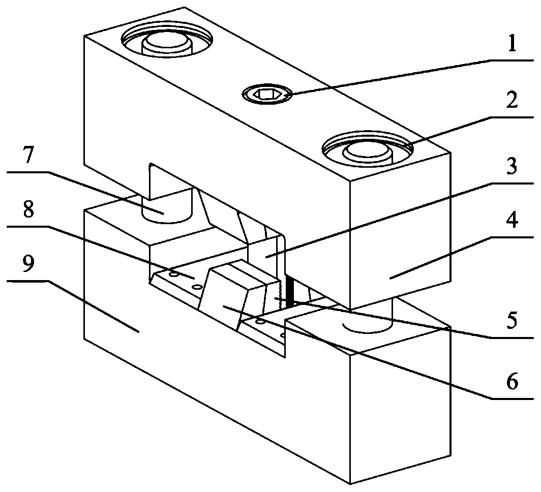
[0026] An embodiment of the present invention provides a fixture for off-axis compression of a composite laminate, comprising an upper base body 4 and a lower base body 9, and the upper base body 4 and the lower base body 9 are slidably connected in the vertical direction through a sliding assembly;
[0027] The opposite end of the upper base body 4 and the lower base body 9 is provided with a clamping structure for clamping the end of the test piece 3, and each base is provided with a clamping structure for pressing the end of the test piece 3 along the longitudinal direction. The briquetting block 10 and a loading structure for applying load to the corresponding briquetting block 10; each seat body is located on the left and right sides of the test piece 3 and is respectively detachably connected with a side stopper 8 for restricting the left and right movement of the test piece 3.
[0028] Further, the clamping structure includes clamp jaws 6 opened on the base, the test pie...
Embodiment 2
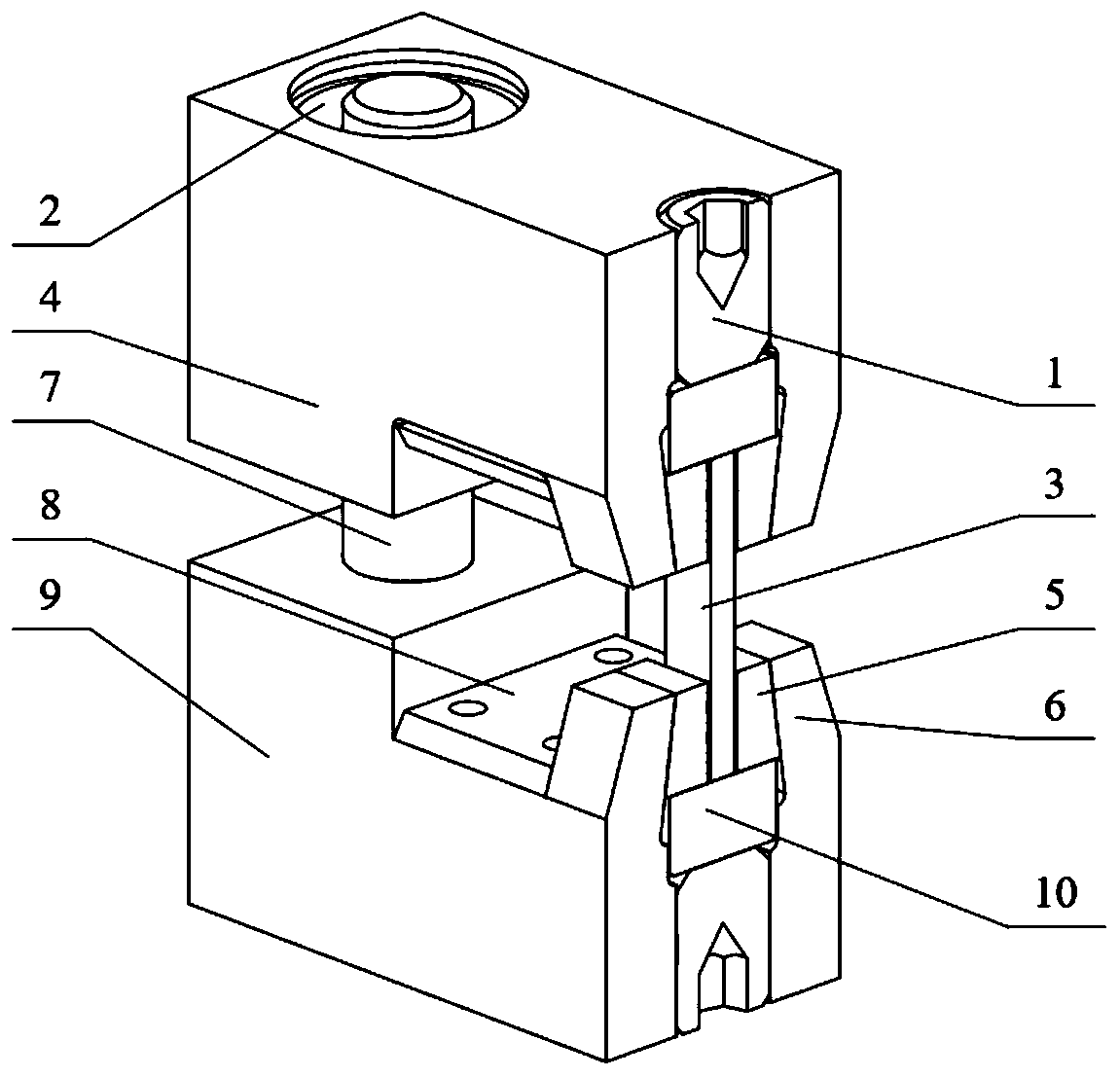
[0036] This embodiment is based on Embodiment 1, the side of the gripping block 5 in contact with the clamped surface of the test piece 3 is a toothed surface, and the toothed surfaces of the clamping blocks 5 on both sides of the test piece 3 are parallel to each other so as to be parallel to the test piece 3 The two clamped surfaces are tightly fitted.
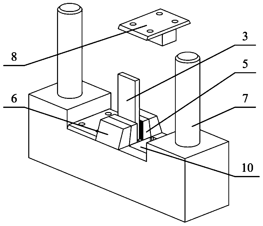
[0037] In this application, the clamping block 5 is a wedge-shaped structure, and the contact surface of the clamping block jaw 6 and the clamping block 5 is also a wedge-shaped slope, the wedge-shaped slope is inclined to the center, and the inner slope extends to the upper base 4 or extends to the inside of the lower base 9, Now take the lower base body 9 as an example, the clamp jaw 6 is located in the center of the lower base body 9 and is integrally formed with the lower base body 9; The distance between the tooth lines is equal, and each tooth line is parallel to each other. The lower end of the test piece 3 is clamped...
Embodiment 3
[0039] This embodiment is based on Embodiment 1, the sliding assembly includes a longitudinal guide rod 7, the lower end of the guide rod 7 is fixed on the lower base body 9, the upper end of the guide rod 7 passes through the upper base body 4 and is slidably connected with it, the guide rod 7 The upper end of the rod 7 is also covered with a linear bearing 2, and the linear bearing 2 is fixed inside the upper body 4;
[0040] There are two sliding assemblies, and the two sliding assemblies are symmetrically distributed on the left and right sides of the clamp jaw 6 .
[0041] The guide rod in this application is a long cylindrical structure, and the upper base body 4 and the lower base body 9 are slidably connected by a sliding assembly. When in use, the clamps of the two clamping mechanisms can slide relative to each other, making it suitable for off-axis compression tests of different sizes. Components, and easy to use DIC, strain gauges and other measuring equipment.
[...
PUM
 Abstract
Description
Claims
Application Information