Bottle bottom defect detection system and method

A technology for defect detection and detection, which is applied in the direction of optical testing of flaws/defects, measuring devices, and material analysis through optical means, which can solve the problems of slow bottom detection and error-prone

Pending Publication Date: 2020-06-30
GUANGZHOU PANYU POLYTECHNIC
View PDF0 Cites 1 Cited by
  • Summary
  • Abstract
  • Description
  • Claims
  • Application Information

AI Technical Summary

Problems solved by technology

[0003] In view of this, the embodiment of the present invention provides a bottle bottom defect detection system and method to solve the problem that the detection speed of the bottom of the product to be detected is slow and error-prone

Method used


Image

  • Bottle bottom defect detection system and method
  • Bottle bottom defect detection system and method
  • Bottle bottom defect detection system and method

Examples


Embodiment 1

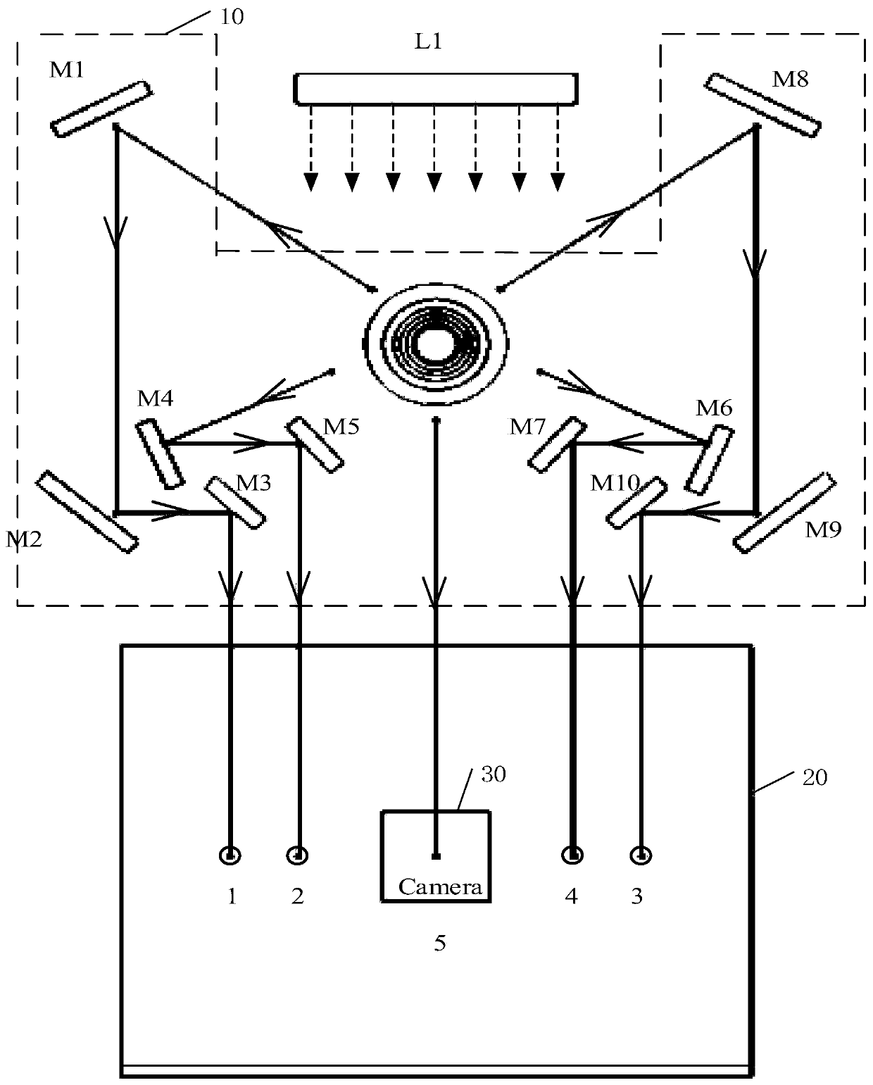
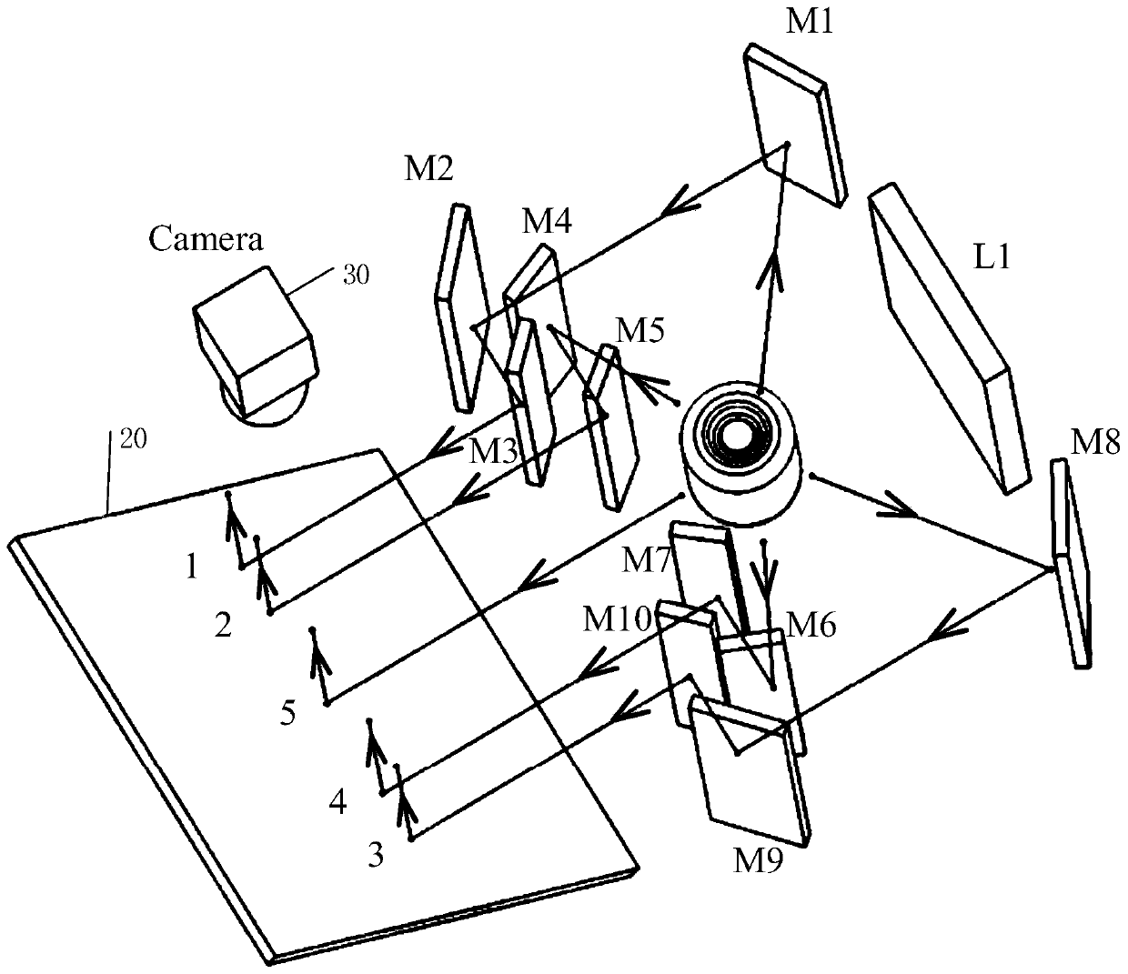
[0041] Such as figure 1 As shown, it is a schematic top view of the optical path structure of the bottle bottom defect detection system provided by Embodiment 1 of the present invention. The bottle bottom defect detection system may include: a light source L1, a mirror array 10, a light collecting device 20, a photographing device 30 and a control device 40;

[0042] Wherein, the system is provided with the light source L1 to irradiate the bottom of the product to be inspected at the detection position (i.e. the C surface of the product to be inspected); Beams of return light carrying bottom information, and respectively transmit the return light reflected by each of the equally divided areas to the light collection device 20; the light collection device 20 reflects the several beams of return light to the within the field of view of the photographing device 30.

[0043]Specifically, since the bottom defect of the product is easy to be ignored during the production process, ...

Embodiment 2

[0060] Such as Figure 4 Shown is a schematic flow chart of the bottle bottom defect detection method provided in Embodiment 2 of the present invention. This embodiment is applicable to the scene where the bottle bottom defect detection system in Embodiment 1 performs defect detection on the bottom (bottom) of the product to be inspected. This method can be executed by the control device 40, which can be an intelligent terminal, tablet or PC, etc. In the embodiment of the present invention, the control device 40 in the bottle bottom defect detection system is used as the execution subject for description, and the method specifically includes the following steps:

[0061] S210. Receive a detection signal sent by a photoelectric sensor disposed at the detection position;

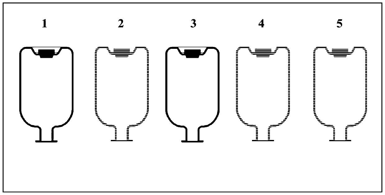
[0062]The bottom of the product to be inspected can be divided into several equal parts according to the requirements. When the product transmission device installed on the assembly line transports the produc...

Embodiment 3

[0075] Figure 7 It is a structural schematic diagram of the control device of the bottle bottom defect detection system provided by the third embodiment of the present invention. The control device includes: a processor 70, a memory 71, and a computer program 72 stored in the memory 71 and operable on the processor 70, such as a program of a method for detecting defects at the bottom of a bottle. When the processor 70 executes the computer program 72, it implements the steps in the above working mode switching method embodiment, for example image 3 Steps S210 to S230 are shown.

[0076] Exemplarily, the computer program 72 can be divided into one or more modules, and the one or more modules are stored in the memory 71 and executed by the processor 70 to complete the present application. The one or more modules may be a series of computer program instruction segments capable of accomplishing specific functions, and the instruction segments are used to describe the execution...


PUM


Abstract

The invention provides a bottle bottom defect detection system and method. The system comprises a light source, a reflector array, a light collecting device, a shooting device and a control device; the light source irradiates the bottom of a to-be-detected product at a detection position; the reflector array receives a plurality of beams of return light carrying bottom information and reflected bya plurality of equally-divided areas at the bottom, and transmits the return light reflected by each equally-divided area to the light collecting device; the light collecting device reflects the plurality of beams of return light into the visual field range of the shooting device in a non-overlapping manner; the shooting device generates a bottom image comprising each equally-divided area according to the plurality of beams of collected return light, and sends the bottom image to the control device; and the control device identifies the bottom defects of the product according to the bottom image and outputs a result. The problems of low human eye visual detection speed, low detection precision and error proneness are overcome.

Description

technical field [0001] The invention relates to the technical field of automatic optical detection, in particular to a defect detection system and method for the bottom of a transparent medicine bottle. Background technique [0002] At present, for the defect detection of the bottom of industrially produced products, such as the bottom of transparent medicine bottles, the most common and traditional method is manual visual inspection, which uses human eyes to check whether there are defects at the bottom of transparent medicine bottles. However, the visual method is time-consuming, labor-intensive, low-efficiency, and subjective factors are greatly affected. Moreover, with the prolongation of the inspection time, it is easy to cause visual fatigue of the inspectors, thereby increasing the rate of missed detection of defects. In the production process of the production line, it is not only time-consuming and labor-intensive to rely on manual inspection, but also many small de...

Claims


Application Information

Patent Timeline
Patent Type & Authority Applications(China)
IPC IPC(8): G01N21/01G01N21/90
CPCG01N21/01G01N21/90
Inventor 钟球盛侯文峰吴隽陈雄杨兴波庞炯林
Owner GUANGZHOU PANYU POLYTECHNIC
Why Eureka
Try Eureka