A high voltage circuit breaker

A high-voltage circuit breaker and main body technology, which is applied in the field of contact boxes for high-voltage (3.6-40.5kV) switchgear, can solve the problems of large occupied volume, large heat generation, complex structure of circuit breakers, etc., and achieve the effect of simple structure

Active Publication Date: 2021-10-29
浙江东禾工程设计有限公司
View PDF11 Cites 2 Cited by
  • Summary
  • Abstract
  • Description
  • Claims
  • Application Information

AI Technical Summary

Problems solved by technology

[0003] The first structure of the contact box is to design a separate valve between the moving contact and the static contact. When the moving contact on the circuit breaker is to be connected with the static contact, the valve is firstly moved by the transmission mechanism during the movement process. Open, the moving contact is connected with the static contact, and the valve and the moving contact are driven by different driving mechanisms respectively. The structure of the circuit breaker adopting this design is too complicated
[0004] The second structure of the contact box is to insert a temporary partition between the moving contact and the static contact instead of the valve. When the moving contact needs to enter the contact box and contact the static contact, the partition is pulled out. This method The operation is cumbersome and occupies a large volume
[0005] Moreover, when the two kinds of contact boxes are in use, due to the contact between the moving contact and the static contact, the heat is huge, and the heat will not dissipate in the contact box for a long time, which will affect the ability of the circuit breaker to carry current and also affect the contact. The service life of the head box and the dynamic and static contacts

Method used


Image

  • A high voltage circuit breaker
  • A high voltage circuit breaker
  • A high voltage circuit breaker

Examples


Embodiment Construction

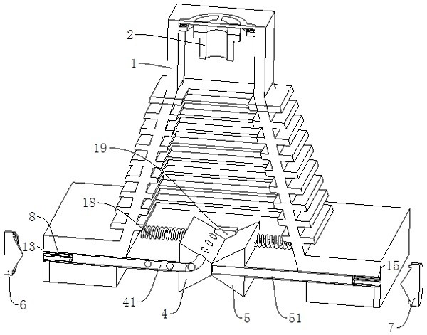
[0035] Combine below Figure 1 to Figure 5 , the present invention is further described:

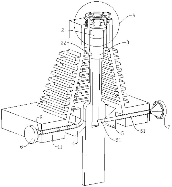
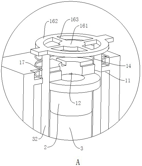
[0036] A high voltage circuit breaker such as Figure 1-3 As shown, the contact box body 1 with the bottom opening is included, the static contact 2 of the circuit breaker is arranged on the first inner wall 11 of the contact box body 1 facing the opening, and the moving contact 3 of the circuit breaker is arranged on the contact box body 1 In addition, the top of the moving contact 3 can enter the contact box body 1 through the opening to contact the static contact 2, thereby forming a conductive circuit.

[0037] The contact box body 1 is provided with a left valve 4 and a right valve 5 with an arrow-shaped cross-section. The arrow ends of the left valve 4 and the arrow ends of the right valve 5 can approach and resist each other, thereby closing the opening. The 3-way contact of the movable contact When the head box body 1 moves inside, the movable contact 3 is opposed to the slope ...


PUM


Abstract

The invention relates to a high-voltage circuit breaker, which comprises a contact box body, and a left valve and a right valve with arrow-shaped cross-sections are arranged in the contact box body, and the arrow ends of the left valve and the arrow ends of the right valve can be close to each other and closed Opening, when the moving contact moves into the contact box body, the moving contact is against the left valve and the right valve, so that the left valve and the right valve can move back to open the opening; the inner cavity of the contact box body passes through the first cycle The air duct communicates with the external space, including a first air inlet duct and a first air outlet duct, the first air inlet duct includes a first air inlet hole arranged on the first inner wall, and the first air outlet duct includes a The first air duct and the first air outlet on the side wall of the contact box body; the outside of the contact box body is provided with a first heat dissipation fan with an air inlet facing the first air outlet. When the first heat dissipation fan works, pressure is generated. Poor, the air in the inner cavity of the contact box body is drawn out, and the air outside the contact box body enters the contact box body at the same time.

Description

technical field [0001] The invention relates to a contact box for high-voltage (3.6-40.5kV) switchgear, in particular to a high-voltage circuit breaker. Background technique [0002] In order to achieve the purpose of shielding the charged body (static contact) during maintenance, the contact box of the circuit breaker in the prior art has the following two structures: [0003] The first structure of the contact box is to design a separate valve between the moving contact and the static contact. When the moving contact on the circuit breaker is to be connected with the static contact, the valve is firstly moved by the transmission mechanism during the movement process. Open, the movable contact is connected with the static contact again, and the valve and the movable contact are respectively driven by different driving mechanisms. The structure of the circuit breaker adopting this design is too complicated. [0004] The second structure of the contact box is to insert a tem...

Claims


Application Information

Patent Timeline
Patent Type & Authority Patents(China)
IPC IPC(8): H01H71/02H01H9/52
CPCH01H9/52H01H71/02H01H2009/526
Inventor 方健美徐思敬蔡海峰喻晓苹胡余龙周晓光黄晓源
Owner 浙江东禾工程设计有限公司
Why Eureka
Try Eureka