Rotary tillage flattening ditcher

A ditching machine and horizontal opening technology, which is applied in the direction of excavation/covering ditches, planting methods, agricultural machinery and tools, etc., can solve the problems of only ditches and broken soil, but cannot be flattened, and fallen into, to achieve The effect of wide application range, improving efficiency and avoiding damage

Pending Publication Date: 2020-07-03
BAODING ZHONGSEN MACHINERY MFG CO LTD
View PDF0 Cites 1 Cited by
  • Summary
  • Abstract
  • Description
  • Claims
  • Application Information

AI Technical Summary

Problems solved by technology

[0002] Due to its simple structure, low cost, easy disassembly and assembly, good ditching quality, high efficiency, and the functions of ditching, crushing soil and weeding, it is now widely used in farmland reclamation and cultivation operations, yam soil preparation operations, and gardening Greening operations, etc. However, the existing ditching machines have relatively shallow ditches and cannot adapt to the planting of some crops that require deep ditching, especially the planting of yams, and the ditching machines can only ditch broken soil during operation. The distance between the trenches cannot be adjusted, and the soil after the trench cannot be flattened, so the soil on the sides after the trench can easily fall into the trench again, reducing the efficiency of the trench

Method used


Image

  • Rotary tillage flattening ditcher
  • Rotary tillage flattening ditcher
  • Rotary tillage flattening ditcher

Examples


Embodiment Construction

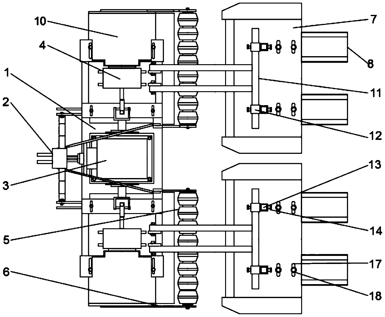
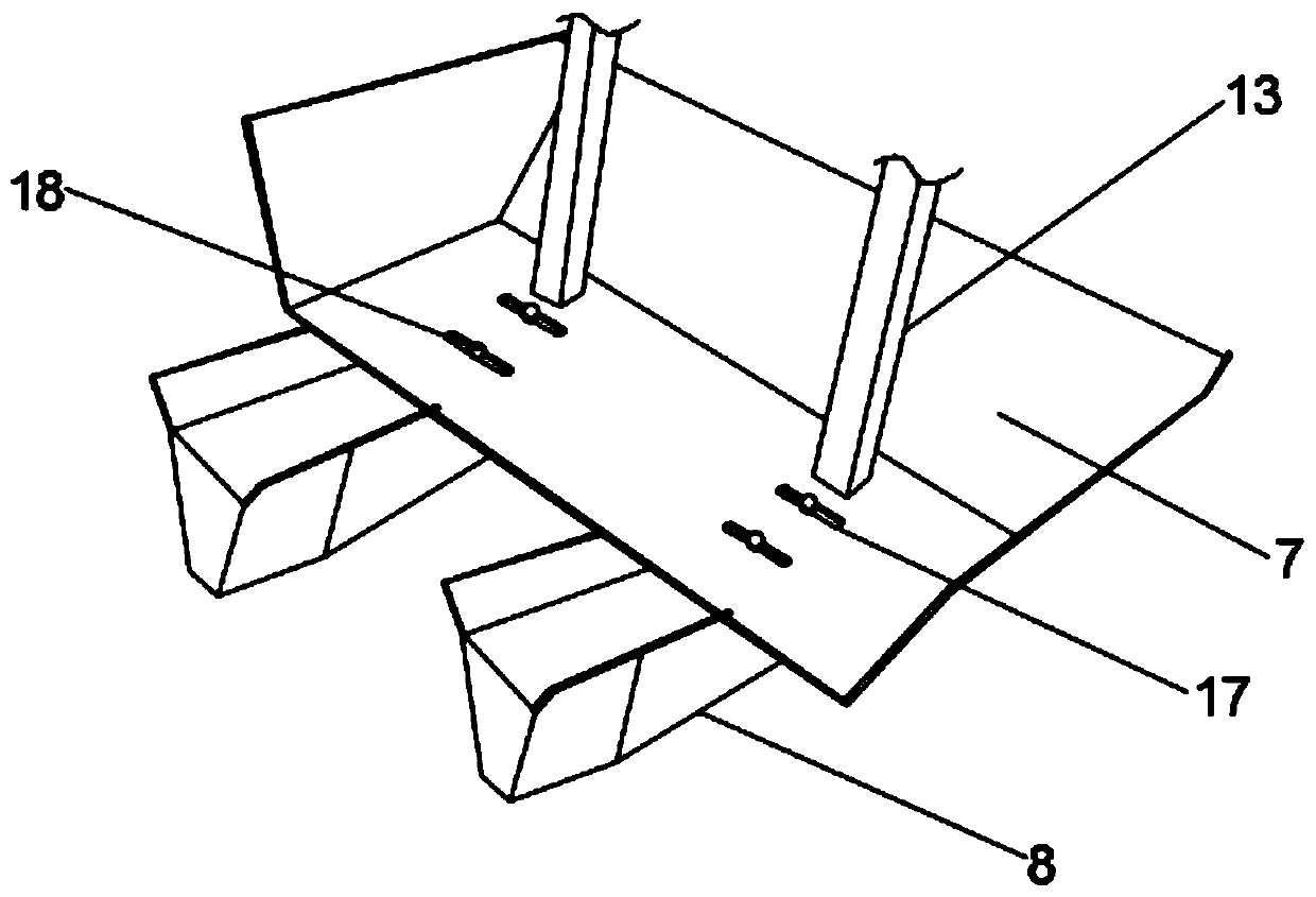
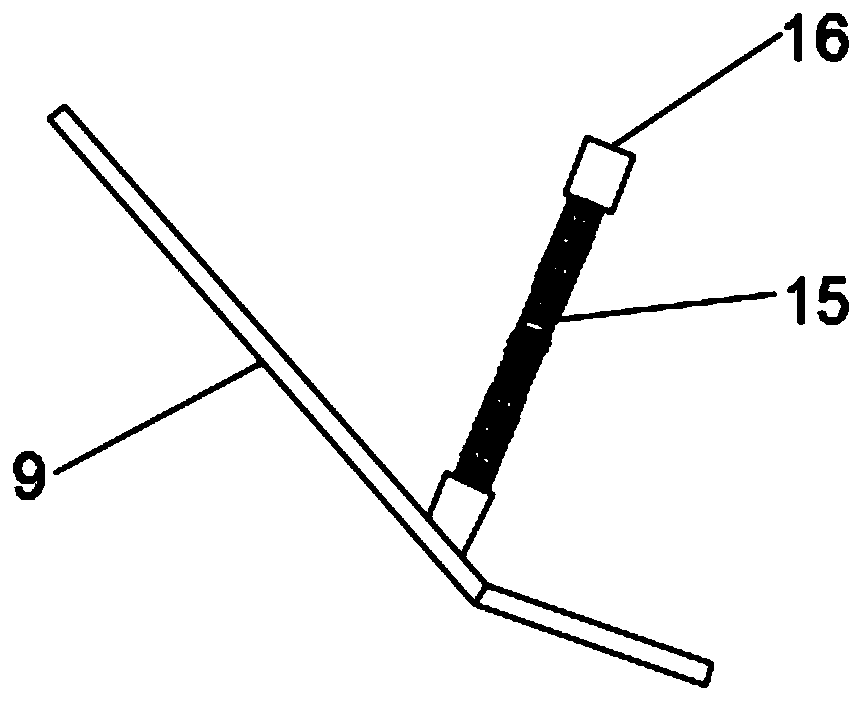
[0022] Such as Figure 1-3 As shown, a rotary tillage leveling ditching machine includes a frame 1, a traction frame 2 is installed on the top of the frame 1, a hydraulic cylinder is arranged on the traction frame 2, and a hydraulic cylinder is installed on the top of the frame 1. There is a fertilizer box, and the two ends of the frame 1 are respectively movably connected with rotary tillage devices, and soil separators are installed on the outsides of the two rotary tiller devices. A pressing plate 9 is arranged between the two rotary tillage devices, and the pressing plate 9 is installed under the frame 1 through a shock absorbing assembly. The shock absorbing device includes a spring 15 and a mount 16, and the spring Both ends of 15 are respectively fixed on the pressing plate 9 and the frame 1 through the mounting base 16 .

[0023] The top of the frame 1 is installed with a transmission device 3 for driving the rotary tiller, the transmission device is movably connected...


PUM


Abstract

The invention discloses a rotary tillage flattening ditcher. The rotary tillage flattening ditcher comprises a rack, wherein a traction frame is installed above the rack, rotary tillage devices are connected to the two ends of the rack respectively, and a flattening plate is arranged between the rotary tillage devices; a transmission device is installed above the rack and movably connected with atransmission assembly of the rotary tillage device; compactors is arranged behind the rotary tillage devices, the two ends of the compactors are movably connected to baffle plates, a ditching device is arranged behind each compactor and installed on the corresponding rotary tillage device, each ditching device comprises a soil pressing plate and ditchers, the ditchers are installed below the corresponding soil pressing plate, the distance between the ditchers can be adjusted, the front ends of the ditchers are sharp ends, and the rear ends of the ditches are trapezoid. According to the rotarytillage flattening ditcher, large soil blocks brought up can be smashed through the compactors, the ditching distance can be controlled through the rotary tillage devices and the ditching devices which can adjust the distance, soil brought out by ditching can be compacted and flattened through the soil pressing plates and the flattening plate, and the land leveling ditching efficiency is improved.

Description

technical field [0001] The invention relates to the technical field of agricultural machinery, in particular to a rotary tillage flattening ditching machine. Background technique [0002] Due to its simple structure, low cost, easy disassembly and assembly, good ditching quality, high efficiency, and the functions of ditching, crushing soil and weeding, it is now widely used in farmland reclamation and cultivation operations, yam soil preparation operations, and gardening Greening operations, etc. However, the existing ditching machines have relatively shallow ditches and cannot adapt to the planting of some crops that require deep ditching, especially the planting of yams, and the ditching machines can only ditch broken soil during operation. The distance between ditching cannot be adjusted, and the soil after ditching cannot be flattened, so that the soil on the sides after ditching is easy to fall into the ditch again, reducing the ditching efficiency. Contents of the i...

Claims


Application Information

Patent Timeline
Patent Type & Authority Applications(China)
IPC IPC(8): A01B49/02A01B49/04A01C5/06
CPCA01B49/02A01B49/04A01C5/062
Inventor 梁蕾
Owner BAODING ZHONGSEN MACHINERY MFG CO LTD
Why Eureka
Try Eureka