Arm unfolding gripper mechanism of industrial robot

A technology of industrial robots and spreading arms, used in manipulators, manufacturing tools, chucks, etc., can solve the problems of inaccurate grasping of workpieces, restricting enterprises, difficult to control position adjustment, etc., to achieve convenient and rapid positioning and pre-compression, and improve work efficiency. , the effect of eliminating steric hindrance

Pending Publication Date: 2020-07-03
项淮智能科技(长兴)有限公司
View PDF0 Cites 0 Cited by
  • Summary
  • Abstract
  • Description
  • Claims
  • Application Information

AI Technical Summary

Problems solved by technology

[0002] In the field of mechanical processing, robot technology has been widely used due to its high precision and high efficiency. On the existing automatic loading and unloading equipment in the mechanical industry automation industry, the position of the workpiece is adjusted when the gripper mechanism of the industrial robot grabs the workpiece. It is difficult to control, the gripper mechanism has the phenomenon of not grasping the workpiece tightly or grasping the workpiece, and the structure is also too thin, there are defects such as deformation, poor precision and low life. In some special industries, the added parts The shape is complex, and the industrial robot gripper of general automatic loading and unloading equipment cannot grasp, grasp or grasp the workpiece accurately, which leads to the unrealization or low efficiency of the automatic production line of the product, and the high maintenance cost, which restricts the production capacity of the enterprise's automatic production line caused certain economic losses and low cost performance

Method used


Image

  • Arm unfolding gripper mechanism of industrial robot
  • Arm unfolding gripper mechanism of industrial robot
  • Arm unfolding gripper mechanism of industrial robot

Examples


Embodiment Construction

[0020] The specific implementation manners of the present invention will be further described in detail below in conjunction with the accompanying drawings and embodiments. The following examples are used to illustrate the present invention, but are not intended to limit the scope of the present invention.

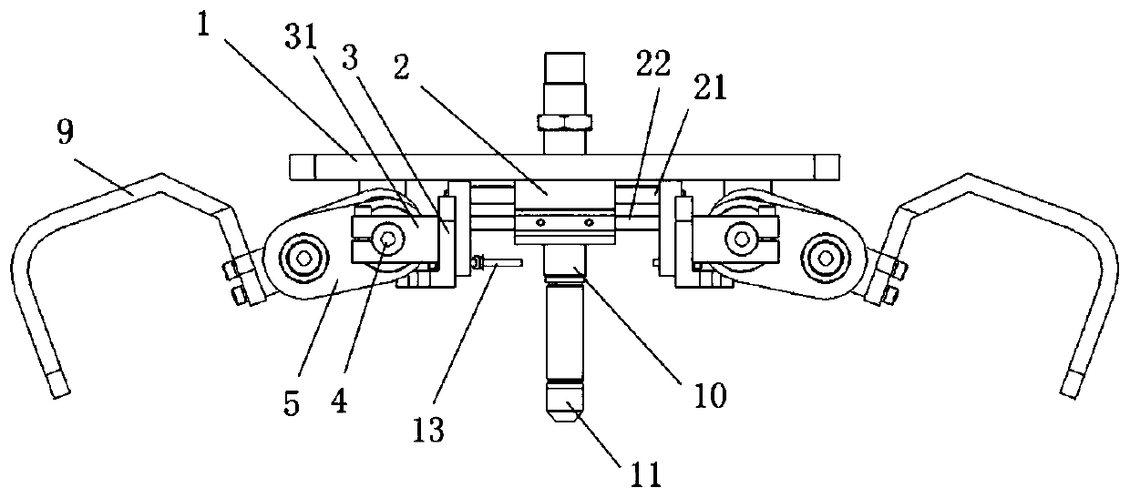
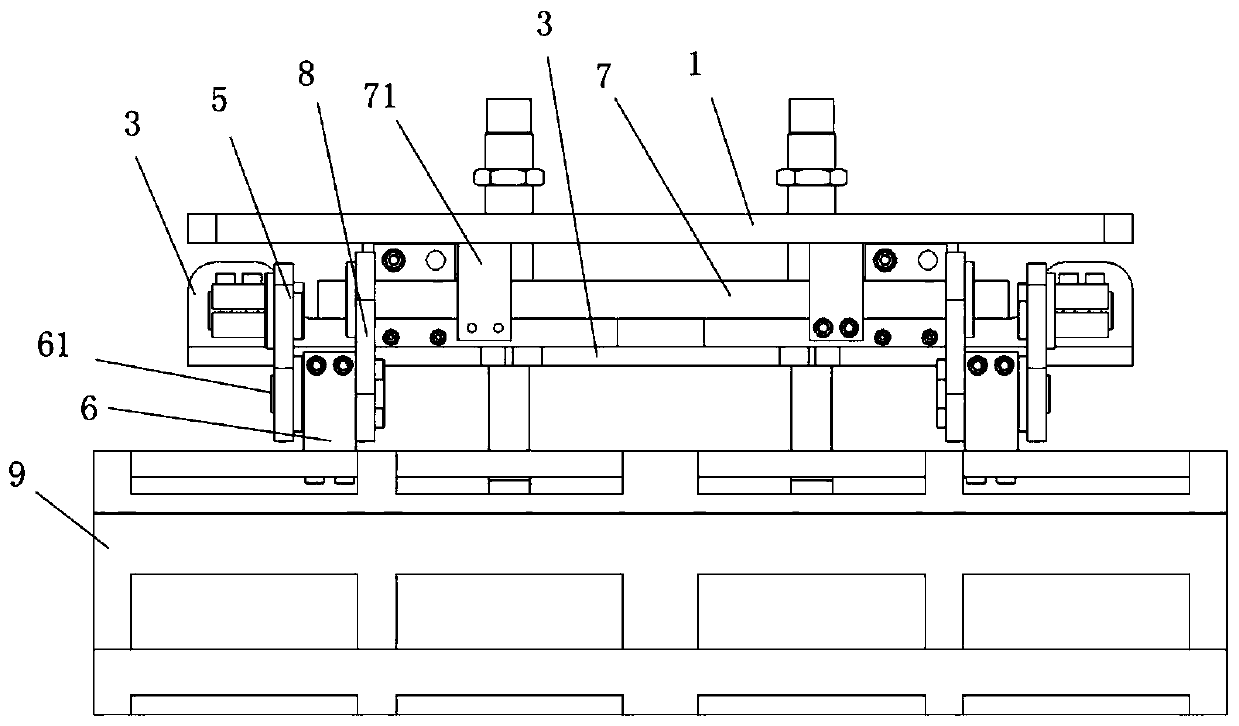
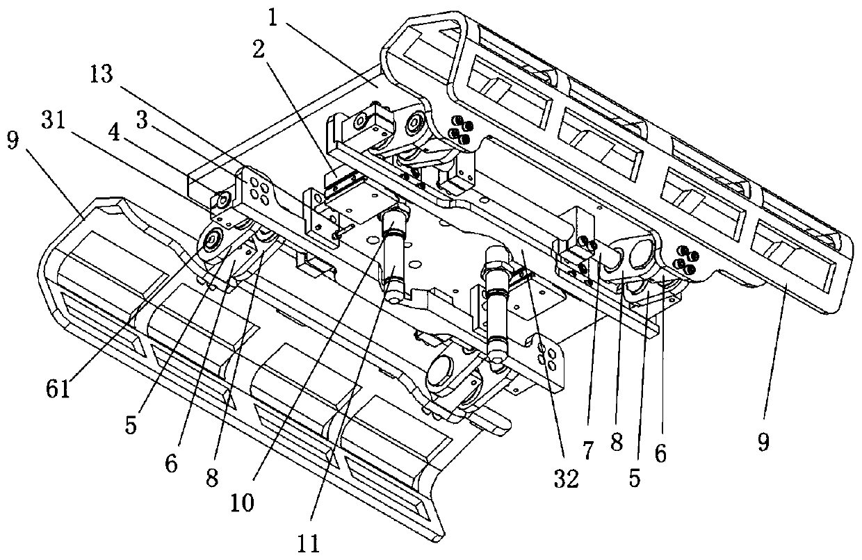
[0021] The invention provides an arm gripper mechanism of an industrial robot, such as Figure 1 ~ Figure 4 As shown, it includes a grip frame 1, a driving device 2, a push firmware 3, a moving arm 5, a fixed arm 8, a fixed shaft 7 and a gripper 9. The driving device 2 is installed at the lower end of the grip frame 1, and the driving device 2 The push rods 21 on the left and right sides are respectively equipped with a pusher 3, and one side of the pusher 3 is provided with a pusher 31, and one end of the moving arm 5 is rotatably installed on the sidewall of the pusher 31, and the other end of the moving arm 5 One end is rotatably installed on one end of the fixed arm 8...


PUM


Abstract

The invention provides an arm unfolding gripper mechanism of an industrial robot. The arm unfolding gripper mechanism comprises a gripper frame, a driving device, a pushing fixing piece, a movable rotating arm, a fixed rotating arm, a fixed shaft and push rods on the two sides of the gripper driving device, wherein the push rods drive the pushing fixing piece to horizontally move towards the two sides, the pushing fixing piece pushes the movable rotating arm and the fixed rotating arm to move, so that the movable rotating arm and the fixed rotating arm do composite motion; the inclination angle of the fixed rotating arm is changed while the fixed rotating arm moves outwards, the fixed rotating arm is gradually inclined from the vertical direction to the outside, and the fixed rotating armdrives a gripper to move, so that the gripper is opened towards the two sides; and when the driving device tightens the pushing fixing piece, the angle of the fixed rotating arm is gradually changed to the vertical direction, the fixed rotating arm drives the gripper to move, so that the gripper is tightened towards the inner side. According to the arm unfolding gripper mechanism, large-stroke movement of the gripper is realized through a small-stroke movement mechanism, and the capacity of the gripper is improved. The arm unfolding gripper mechanism is ingenious in structure, elegant in appearance, capable of rapidly and effectively driving the gripper to move, capable of guaranteeing that automatic feeding and discharging equipment is smooth and stable during working, high in applicability and beneficial to assembly, disassembly and maintenance.

Description

technical field [0001] The invention relates to the technical field of industrial robots, in particular to an arm gripper mechanism of an industrial robot. Background technique [0002] In the field of mechanical processing, robot technology has been widely used due to its high precision and high efficiency. On the existing automatic loading and unloading equipment in the mechanical industry automation industry, the position of the workpiece is adjusted when the gripper mechanism of the industrial robot grabs the workpiece. It is difficult to control, the gripper mechanism has the phenomenon of not grasping the workpiece tightly or grasping the workpiece, and the structure is also too thin, there are defects such as deformation, poor precision and low life. In some special industries, the added parts The shape is complex, and the industrial robot gripper of general automatic loading and unloading equipment cannot grasp, grasp or grasp the workpiece accurately, which leads to...

Claims


Application Information

Patent Timeline
Patent Type & Authority Applications(China)
IPC IPC(8): B25J15/08
CPCB25J15/08
Inventor 胡德山任耀庭罗云秋
Owner 项淮智能科技(长兴)有限公司
Why Eureka
Try Eureka