
Integrated electronic hydraulic brake system

A hydraulic braking, integrated technology, applied in the direction of brake safety system, brake control system, brake, etc., can solve the problems of difficult hydraulic pipeline layout, complex system, inconvenient installation, etc., to reduce system complexity, transmission High efficiency and easy installation effect

Pending Publication Date: 2020-07-03
JILIN UNIV
View PDF0 Cites 0 Cited by
  • Summary
  • Abstract
  • Description
  • Claims
  • Application Information

AI Technical Summary

Problems solved by technology

[0004] The purpose of the present invention is to provide an integrated electronic hydraulic braking system in order to solve the problems of complex system, difficult hydraulic pipeline layout and inconvenient installation on real vehicles caused by the split structure of the current electronic hydraulic braking system.

Method used


Image

  • Integrated electronic hydraulic brake system
  • Integrated electronic hydraulic brake system
  • Integrated electronic hydraulic brake system

Examples


Embodiment Construction

[0034] see Figure 1 to Figure 3 Shown:

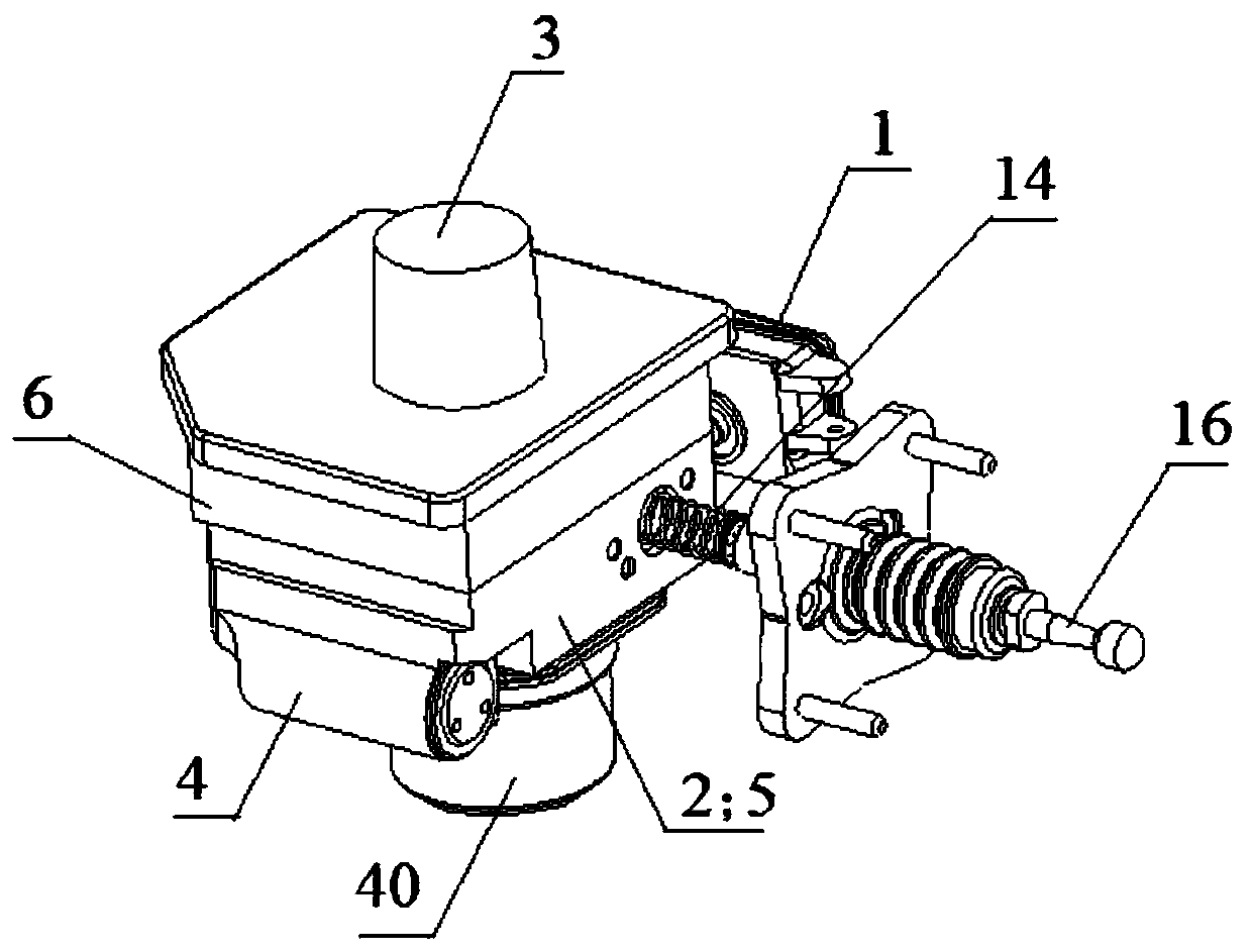
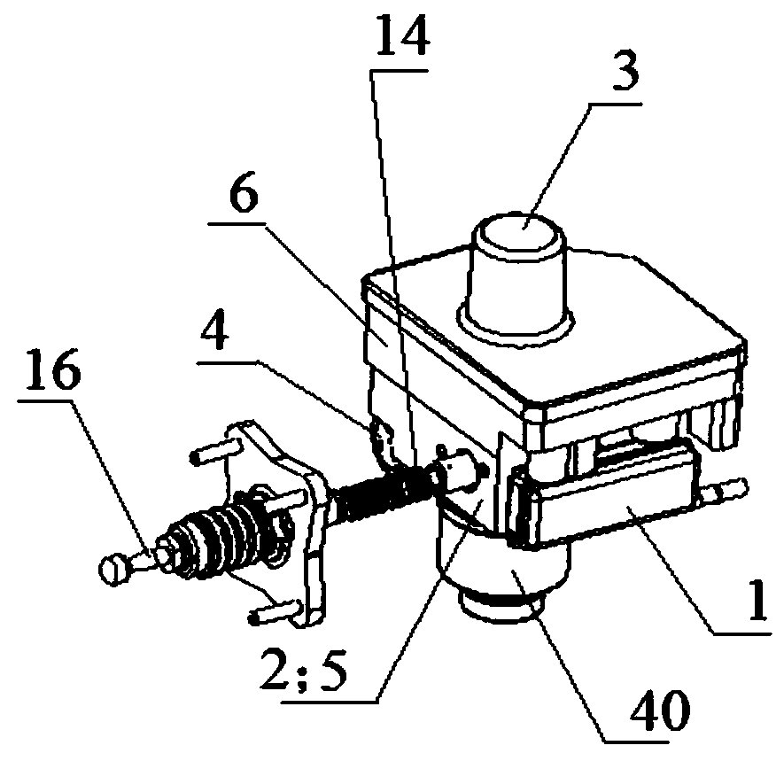
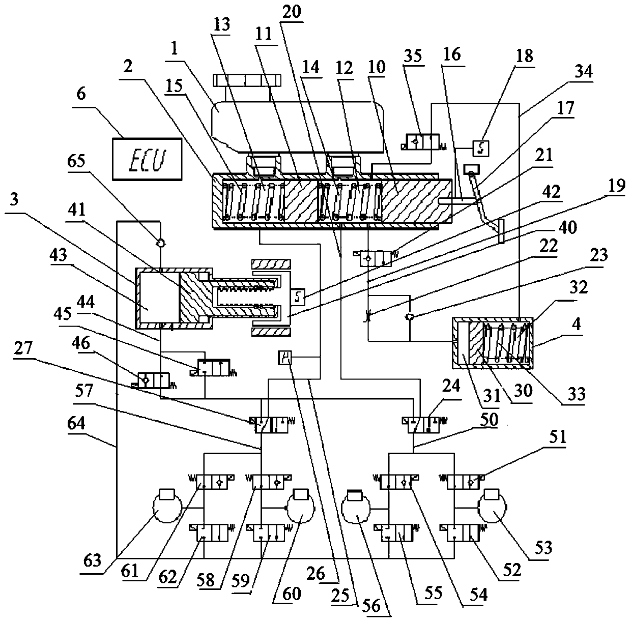
[0035] The integrated electronic hydraulic braking system provided by the present invention includes a fluid storage tank 1, a brake master cylinder 2, an electric pressure building cylinder 3, a pedal feeling simulator 4, a hydraulic control unit 5 and an electronic control unit 6, wherein the fluid storage tank 1. The brake master cylinder 2, the electric pressure building cylinder 3, the pedal feeling simulator 4, the hydraulic control unit 5 and the electric control unit 6 are integrated into a whole structure, and the fluid storage tank 1 is installed close to the brake master cylinder 2 and connected with the brake The master cylinder 2 is connected, the brake master cylinder 2 is assembled in the hydraulic control unit 5, the electric control unit 6 is arranged on the upper part of the hydraulic control unit 5, and the electric pressure building cylinder 3 passes through the electric control unit 6 and is also assembled in the h...


PUM


Abstract

The invention discloses an integrated electronic hydraulic brake system. The system comprises a liquid storage tank, a brake master cylinder, an electric pressure buildup cylinder, a pedal feeling simulator, a hydraulic control unit and an electric control unit, wherein the liquid storage tank, the brake master cylinder, the electric pressure buildup cylinder, the pedal feeling simulator, the hydraulic control unit and the electric control unit are integrated into an integral structure; the liquid storage tank is arranged close to the brake master cylinder and is communicated with the brake master cylinder; the brake master cylinder is assembled in the hydraulic control unit; the electric control unit is arranged on the upper portion of the hydraulic control unit; the electric pressure buildup cylinder penetrates through the electric control unit and is also assembled on the upper portion of the hydraulic control unit; the pedal feeling simulator is arranged on one side of the hydraulic control unit; and the liquid storage tank is assembled on the other side of the hydraulic control unit. The brake device has the beneficial effect that enough brake pressure can be established in ashort time. And the functions of active braking, failure backup, braking energy recovery and the like are achieved.

Description

technical field [0001] The invention relates to a hydraulic braking system, in particular to an integrated electronic hydraulic braking system. Background technique [0002] At present, with the continuous development of vehicle intelligence and electrification technology, the traditional vacuum booster braking system is difficult to meet the requirements of smart vehicles and electric vehicles on the braking system. Smart cars require the brake system to have more precise brake pressure control capabilities, faster response speeds, and sufficient active braking capabilities. These conditions can be used as the underlying actuators of intelligent driving assistance systems. Electric vehicles require the braking system to have a certain decoupling capability, that is, the decoupling of the brake pedal force and the motor assist, so that the braking system can cooperate with regenerative braking, recover braking energy to the maximum extent, improve the cruising range of elect...

Claims


Application Information

Patent Timeline
Patent Type & Authority Applications(China)
IPC IPC(8): B60T13/14B60T13/74B60T8/40B60T7/22B60T17/18
CPCB60T13/146B60T13/746B60T13/745B60T8/409B60T7/22B60T17/18B60T2201/022B60T2270/402B60T2270/60
Inventor 朱冰张伊晗赵健靳万里康宇刘彦辰
Owner JILIN UNIV
Learn More