Fully-decoupled electronic hydraulic braking system and corresponding vehicle

A technology of hydraulic braking and electronic control unit, applied in the direction of brakes, vehicle components, brake transmission devices, etc., can solve the problems of large changes in the master cylinder, hidden dangers of reliability and safety, and low braking energy, and achieves a high level of improvement. System safety and reliability, achieve fail-safe, fast response effects

Pending Publication Date: 2016-08-24
上海千顾汽车科技有限公司
View PDF6 Cites 7 Cited by
  • Summary
  • Abstract
  • Description
  • Claims
  • Application Information

AI Technical Summary

Problems solved by technology

Therefore, the current electro-hydraulic brake system is widely used, and one of the common forms is the uncoupled electro-hydraulic brake system. The principle is to load a certain idle stroke on the brake booster parts. The regenerative braking force is provided by the driving motor. After overcoming this idle stroke, the hydraulic brake intervenes to provide the total braking force together with the regenerative braking. This compound braking system retains the mechanical connection between the pedal and the hydraulic system, reliability and High safety, but its recyclable braking energy is less, which deviates from the traditional brake pedal feeling
[0004] A small number of brake systems use a fully decoupled electro-

Method used


Image

  • Fully-decoupled electronic hydraulic braking system and corresponding vehicle
  • Fully-decoupled electronic hydraulic braking system and corresponding vehicle
  • Fully-decoupled electronic hydraulic braking system and corresponding vehicle

Examples


Embodiment Construction

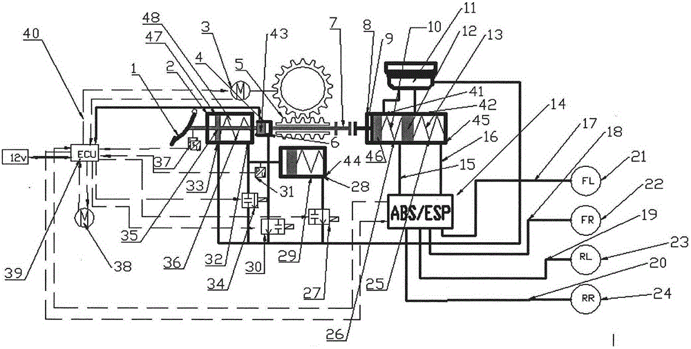
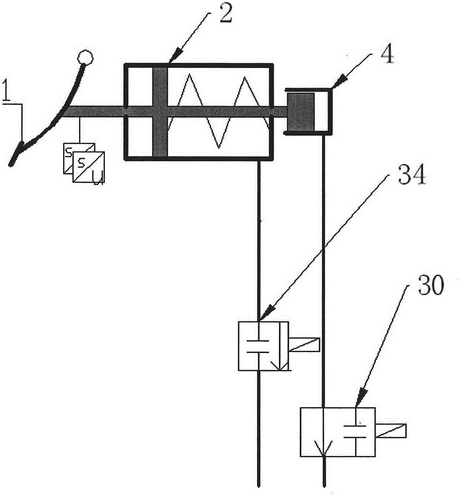
[0042] In order to make the above objects, features and advantages of the present invention more comprehensible, the embodiments of the present invention will be described below in conjunction with the accompanying drawings.

[0043] to combine Figure 1 to Figure 2 As shown, a fully decoupled electronic hydraulic braking system includes: an electronic control unit 39, a motor 3 connected to the electronic control unit 39, a brake pedal displacement sensor 37 connected to the electronic control unit 39, which can be controlled by the The brake pedal displacement sensor 37 detects the brake pedal 1 of its displacement information, the secondary master cylinder 2 connected to the brake pedal 1, the pedal simulator 44 connected to the secondary master cylinder 2, the secondary master cylinder connected to the The decoupling cylinder 4 of the cylinder, the master cylinder 8, and the wheel cylinders 21, 22, 23 and 24 of the brake pipelines 17, 18, 19, 20 and the fluid reservoir 11 ...


PUM


Abstract

The invention discloses a fully-decoupled electronic hydraulic braking system and a corresponding vehicle. The fully-decoupled electronic hydraulic braking system includes a electronic control unit, a motor, a braking pedal displacement sensor, a braking pedal, a secondary main cylinder, a pedal simulator, a decoupling cylinder, a main cylinder, a wheel cylinder, and a liquid storage device; a pipeline between the decoupling cylinder and the liquid storage device is provided with a normally closed solenoid valve of the decoupling cylinder; the main cylinder can be decoupled with the secondary main cylinder through the decoupling cylinder and is driven by the motor or is coupled with the secondary main cylinder and is driven by the secondary main cylinder. The fully-decoupled electronic hydraulic braking system can achieve active control and adjustment of hydraulic pressure without a high pressure energy accumulator, a pump, a hydraulic pipeline, and a solenoid valve, so the fully-decoupled electronic hydraulic braking system has no the problem of potential safety hazard of the high pressure energy accumulator and a disabled solenoid valve; the structure of the fully-decoupled electronic hydraulic braking system is simple, the main cylinder is not needed to be changed, and then the cost is reduced; and failure protection of the braking system can be achieved through interaction of the decoupling cylinder and the normally closed solenoid valve.

Description

technical field [0001] The invention belongs to the technical field of automobile braking, and in particular relates to a fully decoupled electronic hydraulic braking system and a corresponding vehicle. Background technique [0002] At present, the service braking system of a car usually adopts a vacuum-assisted servo braking system, which provides assistance by installing a vacuum booster between the brake pedal push rod and the brake master cylinder. When the vacuum booster provides brake boosting, it needs to provide a vacuum source through the engine's intake manifold or a dedicated vacuum pump. When the engine's intake manifold is used to provide the vacuum source, if the engine is stopped, the vacuum boost effect is lost. In addition, due to environmental protection requirements, the application of pure electric vehicles and hybrid vehicles is increasing. Since electric vehicles replace traditional internal combustion engines with electric motors, the possibility of ...

Claims


Application Information

Patent Timeline
IPC IPC(8): B60T13/66B60T13/68
Inventor 陈晶杰
Owner 上海千顾汽车科技有限公司
Why Eureka
Try Eureka