
Electronic hydraulic brake system with mechanical failure protective function

A fail-safe, hydraulic braking technology, applied in hydraulic braking transmissions, brakes, etc., can solve the problems of less braking energy, pipeline leakage, less recoverable energy, etc., and achieve fast response speed and high safety. , the effect of reducing the risk of system failure

Active Publication Date: 2014-04-30
上海同驭汽车科技有限公司
View PDF5 Cites 25 Cited by
  • Summary
  • Abstract
  • Description
  • Claims
  • Application Information

AI Technical Summary

Problems solved by technology

[0004] The accelerator pedal composite braking system uses the accelerator pedal as the source of the braking intervention signal of the drive motor. This system has minor changes to the original braking system and is easy to control. However, it does not conform to the driver's traditional brake pedal feeling and can be recycled. less energy
[0005] The non-decoupled compound braking system generally loads a certain idle stroke on the original brake booster parts. During this idle stroke, the drive motor provides regenerative braking force. After overcoming this idle stroke, the hydraulic brake intervenes. Regenerative braking provides the total braking force together. This compound braking system retains the mechanical connection between the pedal and the hydraulic system, which has high reliability and safety, but its recyclable braking energy is less, which is different from the traditional brake pedal feel. Deviated
[0006] The fully decoupled composite braking system belongs to the electronic hydraulic braking system. Bosch's HAS hev system and TRW's SCB system are both fully decoupled. The failure protection is divided into hydraulic failure protection and mechanical failure according to the degree of leakage of the hydraulic pipeline. Protection, if it is a small pipeline leak, it will be hydraulic failure protection, if the pipeline leakage is serious, it will be mechanical failure protection, and its master cylinder has changed a lot, usually by installing a high-pressure accumulator Cooperate with the motor and pump to actively control the brake input force of the hydraulic system, but the high-pressure accumulator technology is not yet mature, and there are still hidden dangers in reliability and safety. In addition, the addition of multiple solenoid valves also increases the difficulty and difficulty of control. risk of failure

Method used


Image

  • Electronic hydraulic brake system with mechanical failure protective function
  • Electronic hydraulic brake system with mechanical failure protective function

Examples


Embodiment Construction

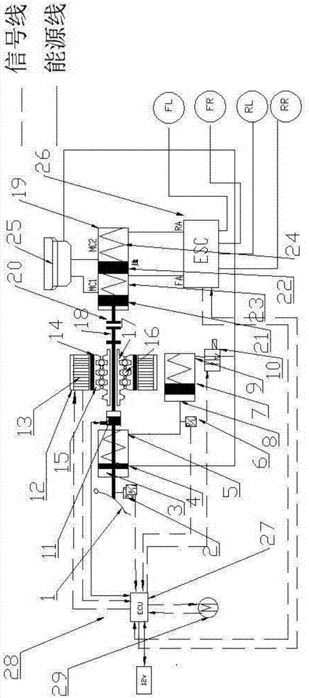
[0026] Such as figure 1 The electro-hydraulic braking system with mechanical failsafe control shown mainly includes a brake pedal 1, a secondary master cylinder 3, a pedal simulator 7, a mechanical failsafe device 11, a motor 12, a motor stator 13, a motor rotor 14, a wire Rod nut 15, ball 16, screw rod 17, linear motion mechanism push rod 18, master cylinder 19, pedal displacement sensor 2, hydraulic pressure sensor 6, solenoid valve 10.

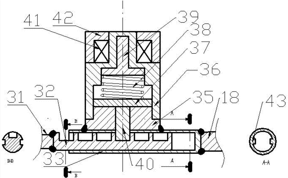
[0027] Such as figure 2 As shown, the mechanical failure protection device 11 mainly includes a bolt lock 32, a bolt lock sleeve 33, a bolt base (aluminum alloy) 35, a bolt shell (aluminum alloy) 36, a moving iron 37, a spring 38, a fixed iron 39, a bolt ( non-ferromagnetic material) 40, electromagnetic coil 41, electromagnetic coil shell (aluminum alloy) 42, latch lock sleeve guide groove 43.

[0028] In this embodiment, the electronically controlled linear motion module includes an electronic control unit 27 , a motor 12 , a motor stat...


PUM


Abstract

An electronic hydraulic brake system with a mechanical failure protective function for vehicles comprises a brake pedal, a pedal displacement sensor, a pedal simulator pressure sensor, a pedal simulator, a pedal simulator electromagnetic valve, a mechanical failure protective device, an electric linear moving module, a brake main cylinder and an ABS / ESC module. In a normal operating mode, a pin lock is separated with a pin lock sleeve; in a failure mode, the pin lock is locked with the pin lock sleeve. The electric linear moving module is use for accurately controlling brake pressure. The brake main cylinder is coupled with a vehicle wheel brake hydraulically through the ABS / ESC module. The ABS / ESC module can passively adjust the pressure of a wheel brake and can also adjust the pressure of one brake of each wheel. The system responds rapidly, accurately, controls the pressure of brake fluid, well simulates the sense of the brake pedal of a driver and recovers brake energy to the utmost extent; a failure protective mode is arranged, the brake pedal and the main cylinder are connected mechanically during failure, and the system has high safety and reliability.

Description

technical field [0001] The invention belongs to the technical field of automobiles and relates to automobile braking technology, in particular to an electronic hydraulic braking system with mechanical failure protection. Background technique [0002] Since petroleum resources are non-renewable resources with limited storage, and the exhaust emissions of fuel vehicles are extremely harmful to the environment, the development of energy-saving and environmentally friendly electric vehicles has become an important direction for major automobile manufacturers. In urban conditions, the car will brake frequently, which will consume a large part of the car's energy. The electro-hydraulic braking system with mechanical failure protection proposed in this paper is used to recover the energy of the electric vehicle during braking. When the vehicle decelerates and brakes, the motor can be used to brake. Due to the lag of the motor during braking, the power supply is reversed to generat...

Claims


Application Information

Patent Timeline
Patent Type & Authority Applications(China)
IPC IPC(8): B60T8/17B60T11/18
Inventor 熊璐汪阳光徐松云余卓平
Owner 上海同驭汽车科技有限公司
Learn More