
Fully-automatic water pump state monitoring and fault diagnosis system

A fault diagnosis system and state monitoring device technology, applied in radial flow pumps, pumps, pump control, etc., can solve problems such as time-consuming and labor-intensive, waste of monitoring resources, and large error in results, so as to improve data processing efficiency and save monitoring Cost, the effect of improving monitoring efficiency

Pending Publication Date: 2020-07-03
江阴市全盛自动化仪表有限公司
View PDF0 Cites 1 Cited by
  • Summary
  • Abstract
  • Description
  • Claims
  • Application Information

AI Technical Summary

Problems solved by technology

[0003] The traditional water pump monitoring method adopts manual reading and manual data input and processing, which is time-consuming and laborious, and data input is also delayed, and the monitoring efficiency is low.
The on-site environment of the traditional water pump unit produces a lot of noise and vibration, and the data collected manually cannot fully reflect the actual working conditions, which will bring various errors, and the monitoring results have large errors
Traditional water pump sensor devices mostly use mechanical structures to measure various parameters. The measurement accuracy is greatly affected by the ambient temperature and humidity as well as the fatigue of the mechanism, and the accuracy of the measured parameters is low.
The traditional monitoring index processing devices are all integrated large chassis, and various index analysis modules are integrated together; when the monitoring points are scattered, and the number of monitored water pumps or the number of indicators changes, the functions of the integrated large chassis cannot be fully used, resulting in Monitor resource waste

Method used


Image

  • Fully-automatic water pump state monitoring and fault diagnosis system
  • Fully-automatic water pump state monitoring and fault diagnosis system
  • Fully-automatic water pump state monitoring and fault diagnosis system

Examples


Embodiment Construction

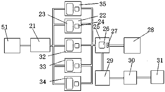
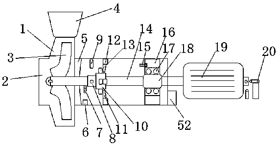
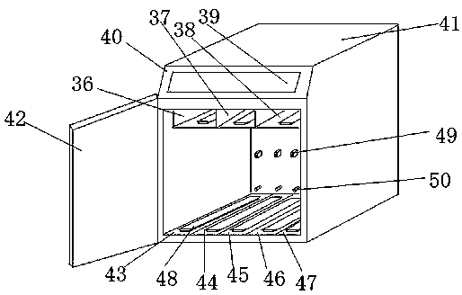
[0017] see Figure 1 to Figure 4 , the present invention relates to a fully automatic water pump state monitoring and fault diagnosis system, comprising a water pump state monitoring device 51, a network signal receiving module 21, a vibration monitoring module 22, a displacement monitoring module 32, a swing monitoring module 33, a temperature monitoring module 34, The speed monitoring module 35, the data output module 25 and the electrical cabinet 41; the water pump state monitoring device 51 is connected to the network signal receiving module 21, and the water pump state monitoring device 51 can transmit the monitored index parameters to the network signal receiving module 21 through the Internet; The network signal receiving module 21 is respectively connected to the vibration monitoring module 22, the displacement monitoring module 32, the swing monitoring module 33, the temperature monitoring module 34 and the rotational speed monitoring module 35, and distributes the rec...


PUM


Abstract

The invention relates to a fully-automatic water pump state monitoring and fault diagnosis system. The fully-automatic water pump state monitoring and fault diagnosis system comprises a network signalreceiving module, which is connected with a vibration monitoring module, a displacement monitoring module, a swing monitoring module, a temperature monitoring module and a rotating speed monitoring module respectively, wherein filter circuits and main chips are arranged inside the monitoring modules; the monitoring modules are connected with a data output module respectively; an information processing module is arranged inside the data output module; a communication module is arranged inside the data output module; the data output module is connected with an information display module; the other interface of the data output module is connected with an Internet of Things module; the Internet of Things module is connected with a cloud server; and the cloud server is connected with mobile end equipment. Through the adoption of the fully-automatic water pump state monitoring and fault diagnosis system, high-accuracy multi-index real-time measurement can be performed; automatic acquisition, real-time transmission and processing of parameters are realized; a monitoring device is modularized; the measuring accuracy is improved; the monitoring efficiency is improved; monitoring errors arereduced; and meanwhile the monitoring cost is lowered.

Description

technical field [0001] The invention relates to a fully automatic water pump state monitoring and fault diagnosis system. Background technique [0002] With the rapid development of the national economy, various large, medium and small water pumps have a wide range of application markets in water conservancy projects, municipal engineering, industry and agriculture, and play an important role in them. During the operation of the pump, different influencing factors such as mechanical factors, hydraulic factors, and electromagnetic factors will cause the vibration, swing and displacement of the pump shaft. The emergence of vibration, swing and displacement problems will cause damage to the pump unit, and even cause major operational failures. The water pump is driven by the shaft in operation, and the rotation speed of the shaft depends on the motor, water resistance and other friction forces, so the rotation speed of the shaft is an important water pump index. At the same t...

Claims


Application Information

Patent Timeline
Patent Type & Authority Applications(China)
IPC IPC(8): F04D15/00F04D13/06F04D1/00F04D29/046
CPCF04D15/0088F04D15/0077F04D13/06F04D1/00F04D29/046F04D29/0462
Inventor 夏军陈虎张永清
Owner 江阴市全盛自动化仪表有限公司
Learn More