Transmission mechanism for electric tool with axial locking function

A technology of transmission mechanism and power tool, which is applied in the direction of manufacturing tools, transmission devices, gear transmission devices, etc., can solve the problem that the locking structure cannot move stably to the locked position, the axial locking device is unstable, and the power tool is slipping when used. problems, to avoid the failure of the shaft lock, increase the torque, and achieve the effect of simple structure

Pending Publication Date: 2020-07-03
扬州佩明传动科技有限公司
View PDF0 Cites 0 Cited by
  • Summary
  • Abstract
  • Description
  • Claims
  • Application Information

AI Technical Summary

Problems solved by technology

[0003] Most of the commonly used power tools do not have the shaft lock function, that is, they cannot be used without power on during daily use. A small number of power tools with the shaft lock function often have certain defects. The most prominent defect...

Method used


Image

  • Transmission mechanism for electric tool with axial locking function
  • Transmission mechanism for electric tool with axial locking function
  • Transmission mechanism for electric tool with axial locking function

Examples


Embodiment 1

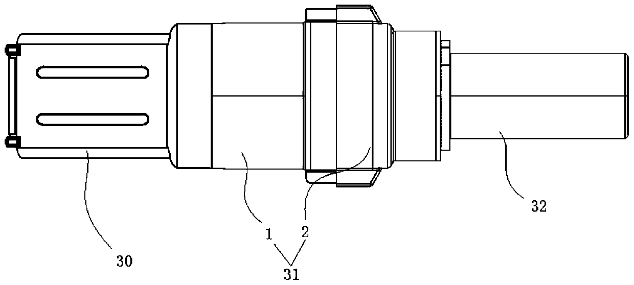
[0044] An electric tool transmission mechanism with a shaft lock function in this embodiment includes a motor 30, a transmission mechanism 31 and an output spindle 32;

[0045] The motor: connected to the transmission mechanism for power output;

[0046] The transmission mechanism: it is composed of a reduction gear box and an axial locking device. The reduction gear box is a planetary gear reduction box, which is used for receiving and transmitting power, and can be self-locking;

[0047]The output spindle: connected to the axial locking device, receives the power transmitted by the axial locking device, and is used to connect the electric tool head and perform output work;

[0048] Wherein, the reduction gear box is connected with the motor transmission, receives the power input by the motor, and outputs to the axial locking device after gear transmission and increased torque; the axial locking device receives the power transmitted by the reduction gear box , and drive to t...

Embodiment 2

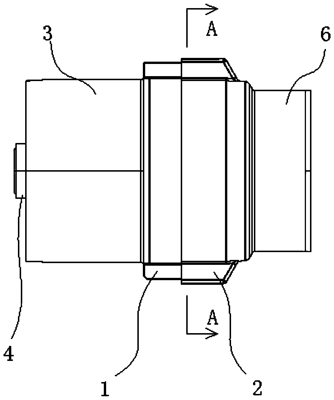
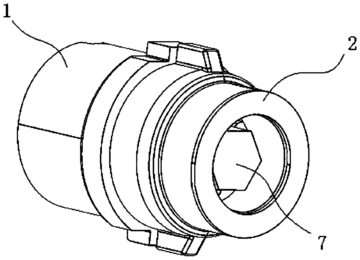
[0050] An electric tool transmission mechanism with a shaft lock function in this embodiment, wherein the reduction gear box 1 includes a speed change inner tooth sleeve 3, an input gear 4 and a transmission planetary gear 5, and the axial locking device 2 includes a shaft Lock protection sleeve 6, shaft lock cam 7, shaft lock pin 8 and shaft lock middle piece 9;

[0051] The variable speed inner gear sleeve 3 is in the shape of a cylindrical tube sleeve, and its inner wall is provided with a ring of internal gear openings 10 distributed in a circle. One end of the variable speed inner gear sleeve 3 is clamped with a limit buckle 11, and the other end is locked with the shaft. The protective sleeve 6 is fixedly connected, and the transmission planetary gear 5 is arranged in the speed change inner gear sleeve 3, including a gear plate 12 and a first transmission gear 13. The gear plate 12 is disc-shaped, and a first rotating shaft is provided on one side 14, the other side is p...

Embodiment 3

[0056] A power tool transmission mechanism with a shaft lock function in this embodiment, wherein the number of the transmission planetary gears 5 is multiple, and a plurality of transmission planetary gears 5 constitute a transmission planetary gear set 24, and the adjacent transmission planetary gears 5 The first transmission gear 13 of the first transmission gear 13 meshes with the transmission rotary gear 15, and the transmission planetary gear 5 at one end of the transmission planetary gear set 24 meshes with the input gear 4 through the first transmission gear 13, and the other end of the transmission planetary gear set 24 meshes with the second transmission gear 171 through the transmission rotary gear 15. The inside meshes to realize the transmission;

[0057] In this embodiment, the number of transmission planetary gears in the reduction gearbox can be increased as required to achieve greater torque output.


PUM


Abstract

The invention discloses a transmission mechanism for an electric tool with an axial locking function. The transmission mechanism is used for power transmission of the electric tool and mainly used forelectric screw drivers and other electric tools. The transmission mechanism comprises a motor, a drive mechanism and an output spindle, wherein the drive mechanism is composed of a reduction gear boxand an axial locking device; the reduction gear box comprises a variable speed inner gear sleeve, an input gear and a drive planet gear; and the axial locking device comprises an axial locking protective jacket, an axial locking cam, axial locking pins and an axial locking middle part. The transmission mechanism is simple in structure and reasonable in design, can increase torsion and has an axial locking effect. Thus, the electric tool applying the transmission mechanism has the function of manual and automatic integration, meanwhile, the axial locking cam combines long pins with short pins,the motion of the axial locking pins is controlled, the stable occurrence of the axial locking effect can be effectively ensured, axial locking failures are avoided, and better use stability is realized.

Description

technical field [0001] The invention relates to the technical field of electric tools, in particular to an electric tool transmission mechanism with a shaft lock function. Background technique [0002] Electric tools refer to tools that use electric energy to do work and output force. It usually includes a work device, a transmission mechanism, and an output mechanism. The work device converts electrical energy into kinetic energy output, and can also be called an input device. After passing, work is done outwards through the output mechanism. Common electric tools include electric screwdrivers, electric screwdrivers and so on. [0003] Most of the commonly used power tools do not have the shaft lock function, that is, they cannot be used without power on during daily use. A small number of power tools with the shaft lock function often have certain defects. The most prominent defect is that the shaft lock function is unstable, that is, in When the power tool is not powere...

Claims


Application Information

Patent Timeline
IPC IPC(8): F16H35/00F16H1/32B25F5/00
CPCB25F5/001F16H35/00F16H2001/327F16H2035/005F16H2035/006
Inventor 李军
Owner 扬州佩明传动科技有限公司
Why Eureka
Try Eureka