
A Diffractive Optical Device for Orthogonal Polarized Light Imaging Based on Metasurface

A technology of orthogonally polarized light and diffractive optics, applied in optical components, optics, instruments, etc., can solve problems such as low efficiency and large volume of polarized imaging components, and achieve the effect of overcoming the theoretical threshold limit

Active Publication Date: 2021-03-12
TSINGHUA UNIV
View PDF19 Cites 0 Cited by
  • Summary
  • Abstract
  • Description
  • Claims
  • Application Information

AI Technical Summary

Problems solved by technology

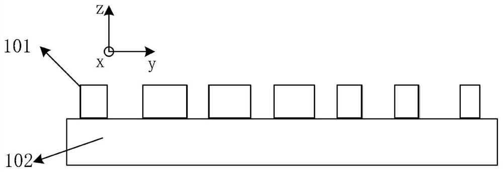
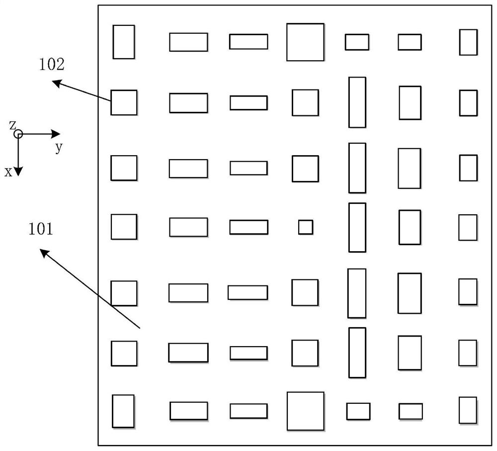
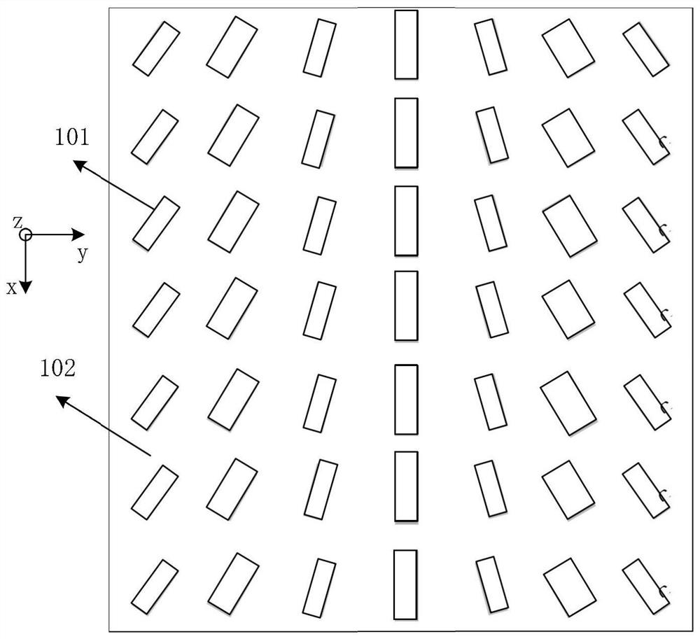
[0005] Aiming at the problems of large volume and low efficiency of polarization imaging components in the prior art, the present invention provides a compact, high-efficiency, polarization splitting and focusing imaging by designing the geometric size and arrangement of sub-wavelength nanocolumn antennas. Integrated Orthogonal Polarized Light Simultaneous Imaging Optics

Method used


Image

  • A Diffractive Optical Device for Orthogonal Polarized Light Imaging Based on Metasurface
  • A Diffractive Optical Device for Orthogonal Polarized Light Imaging Based on Metasurface
  • A Diffractive Optical Device for Orthogonal Polarized Light Imaging Based on Metasurface

Examples


Embodiment Construction

[0038] In order to make the object, technical solution and advantages of the present invention clearer, the present invention will be further described in detail below in conjunction with the accompanying drawings and embodiments. It should be understood that the specific embodiments described here are only used to explain the present invention, and do not limit the protection scope of the present invention.

[0039] In order to better understand the present invention, an application example of a metasurface-based orthogonal linearly polarized light imaging diffractive optical device proposed by the present invention is described in detail below.

[0040] The invention proposes a metasurface-based orthogonal linearly polarized light imaging diffractive optical device, the orthogonal linearly polarized light imaging diffractive optical device consists of a substrate (102, 202) and is arranged on the substrate (102, 202) in the form of an array 202) consisting of several sub-wav...


PUM

PropertyMeasurementUnit
widthaaaaaaaaaa
refractive indexaaaaaaaaaa

Abstract

The invention provides an orthogonal polarized light imaging diffractive optical device based on a super-structure surface. The orthogonal polarized light imaging diffractive optical device is composed of a substrate and sub-wavelength optical antennas arranged on a surface of the substrate in an array mode, wherein the sub-wavelength optical antenna array is a two-dimensional array, directions parallel to the row and the column of the sub-wavelength optical antenna array are used as an x axis and a y axis respectively, the cross section shape of each optical antenna along the xy plane has C2symmetry, the length and the width of each optical antenna are respectively 1 / 20 to 1 / 2 of the working wavelength, the heights of the optical antennas are equal and are in a sub-wavelength range, anda center distance between two adjacent optical antennas is equal and does not exceed half of the working wavelength; the transmission phase is applied to the orthogonal linearly polarized light by designing the length and width of each optical antenna, and the transmission phase and the geometric phase are simultaneously applied to the orthogonal circularly polarized light by designing the lengthand width and the rotation angle of each optical antenna. The orthogonal polarized light imaging diffractive optical device is advantaged in that simultaneous focusing imaging of different positions of the orthogonal polarized light can be realized by using one unit structure.

Description

technical field [0001] The invention can be applied to the fields of orthogonally polarized light imaging and the like, and particularly relates to a metasurface-based orthogonally polarized light imaging diffractive optical device. Background technique [0002] Polarization is one of the fundamental properties of light. Substances will have different polarization characteristics due to their own properties (such as surface properties, roughness, shadow and shape, etc.) (the characteristic polarization determined by their own properties will be generated). Polarization imaging is the process of using the obtained information to reconstruct and enhance the target on the basis of real-time acquisition of target polarization information. Compared with techniques such as intensity imaging, spectral imaging, and infrared radiation imaging, in addition to obtaining traditional imaging information, it can Obtaining polarization information is a cutting-edge technology with great a...

Claims


Application Information

Patent Timeline
Patent Type & Authority Patents(China)
IPC IPC(8): G02B27/28G02B27/00G02B1/00
CPCG02B1/002G02B27/0012G02B27/286
Inventor 杨原牧赵峰
Owner TSINGHUA UNIV
Learn More