A self-resetting switch circuit and control method based on feedback control

A switching circuit and feedback control technology, which is applied in the direction of control/regulation system, regulation of electrical variables, instruments, etc., can solve the problems of inconvenient installation and use, affecting the life of equipment, and large circuit size, so as to achieve small circuit size and prevent abnormal The effect of autonomous power on and off

Active Publication Date: 2021-06-22
SHENYANG SIASUN ROBOT & AUTOMATION
View PDF5 Cites 0 Cited by
  • Summary
  • Abstract
  • Description
  • Claims
  • Application Information

AI Technical Summary

Problems solved by technology

[0003] First of all, when the current is too large, the current limiting requirements are considered, resulting in a very large circuit size, which is inconvenient to install and use; secondly, when the power supply has abnormal phenomena such as power outages and trips, power failure will occur. When the circuit is powered on and restored , the self-locking switch in the conduction state will power on the load equipment immediately. At this time, the surge on the power supply line will have a greater adverse effect on the equipment, especially when the abnormal situation occurs repeatedly, it will make the load equipment frequent Non-autonomous power on and off seriously affects the life of the equipment; in addition, the existing self-locking power switch cannot realize program-controlled shutdown, which is difficult to meet application requirements

Method used


Image

  • A self-resetting switch circuit and control method based on feedback control
  • A self-resetting switch circuit and control method based on feedback control

Examples


Embodiment Construction

[0019] The present invention will be described in more detail below with reference to the accompanying drawings and examples.

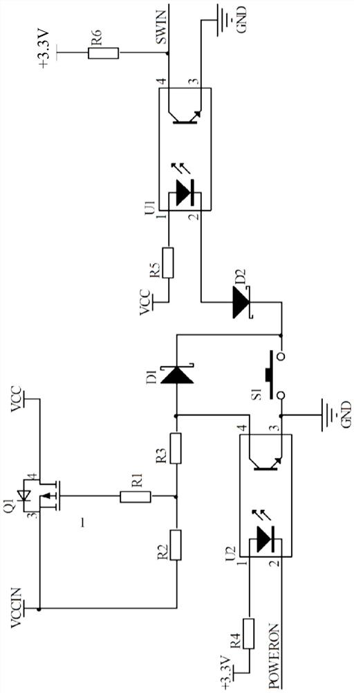
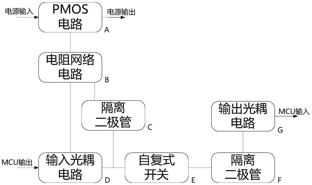
[0020] The present invention discloses a feedback-based self-reciprocating switch circuit, combined figure 1 with figure 2 As shown, it includes a PMOS tube Q1, an input optocoupler U2, an output optocoupler U1, a self-reset switch S1, and a controller, the source of the PMOS tube Q1 as a power input Vccin, the drain of the PMOS tube Q1 As the power supply output terminal Vcc, the source of the PMOS tube Q1 and the gate are connected by the first voltage resistor R2 and the first stream resistance R1 in series, the first voltage resistance R2 and the first limit. The connection point of the stream resistor R1 is connected to the output terminal collector of the input optocoupler U2 by the second voltage resistor R3, and the input light coupling U2 output terminal emitter, the input light coupling U2 input end anode Connecting a high potential 3.3V, the in...


PUM


Abstract

The invention discloses a self-reset switch circuit based on feedback control, which comprises a PMOS tube, an input optocoupler, an output optocoupler, a self-reset switch and a controller. The first voltage dividing resistor is connected to the first current limiting resistor, and the connection point of the first voltage dividing resistor and the first current limiting resistor is connected to the collector of the output end of the input optocoupler through the second voltage dividing resistor, and the input end of the input optocoupler The anode is connected to the high potential, the input terminal cathode of the input optocoupler is connected to the controller, the input terminal anode of the output optocoupler is connected to the power output terminal, and the self-reset switch is connected in series with the input terminal cathode of the output optocoupler and the output terminal of the input optocoupler Between the emitters, the collector of the output end of the output optocoupler is also connected to the controller, and the emitter of the output end of the output optocoupler is grounded. The invention can be applied to a high current environment, helps to reduce the volume of the switch circuit, can reduce the surge impact during abnormal switching on and off, and can prevent the load equipment from being powered on and off involuntarily.

Description

Technical field [0001] The present invention relates to a switching control circuit, and more particularly to a feedback control, a self-reciprocating switching circuit and a control method. Background technique [0002] In the prior art, common self-locking power switching circuits, mostly through two contacts of normally open or normally closed, this turmoil control method has the following three main disadvantages: [0003] First, when the current is too large, consider the current limiting requirements, causing the circuit to be very large, it is inconvenient to install and use; secondly, the power is powered down when the power supply is powered down, trip, and the trip is turned down. When the circuit is recovered on the circuit The self-locking switch in the on state will turn the load device to power up. At this time, the surge on the power line will have a large adverse effect on the equipment, especially when the abnormal situation is repeated, will make the load device...

Claims


Application Information

Patent Timeline
Patent Type & Authority Patents(China)
IPC IPC(8): G05F1/56
CPCG05F1/56
Inventor 邹风山梁策刘新温昌翯刘世昌白宏生
Owner SHENYANG SIASUN ROBOT & AUTOMATION
Why Eureka
Try Eureka