Roll forming machine

A forming machine and rolling technology, which is applied to forming tools, metal rolling stands, metal rolling mill stands, etc., can solve the problems of large-scale and high cost, and achieve the effects of simple replacement operation, simplified structure and simple structure.

Active Publication Date: 2020-07-03
NAKATA MFG
View PDF11 Cites 1 Cited by
  • Summary
  • Abstract
  • Description
  • Claims
  • Application Information

AI Technical Summary

Problems solved by technology

However, since the upper and lower horizontal rollers are in a cantilevered state through the operation side portion of the base frame when the base frame is separated, it is necessary to increase the rigidity of the base frame, which inevitably leads to an increase in size and cost. are limited to rollers with relatively small diameters such restrictions
In addition, the complication of the machine base structure due to the division of the machine base frame cannot be avoided

Method used


Image

  • Roll forming machine
  • Roll forming machine
  • Roll forming machine

Examples


Embodiment Construction

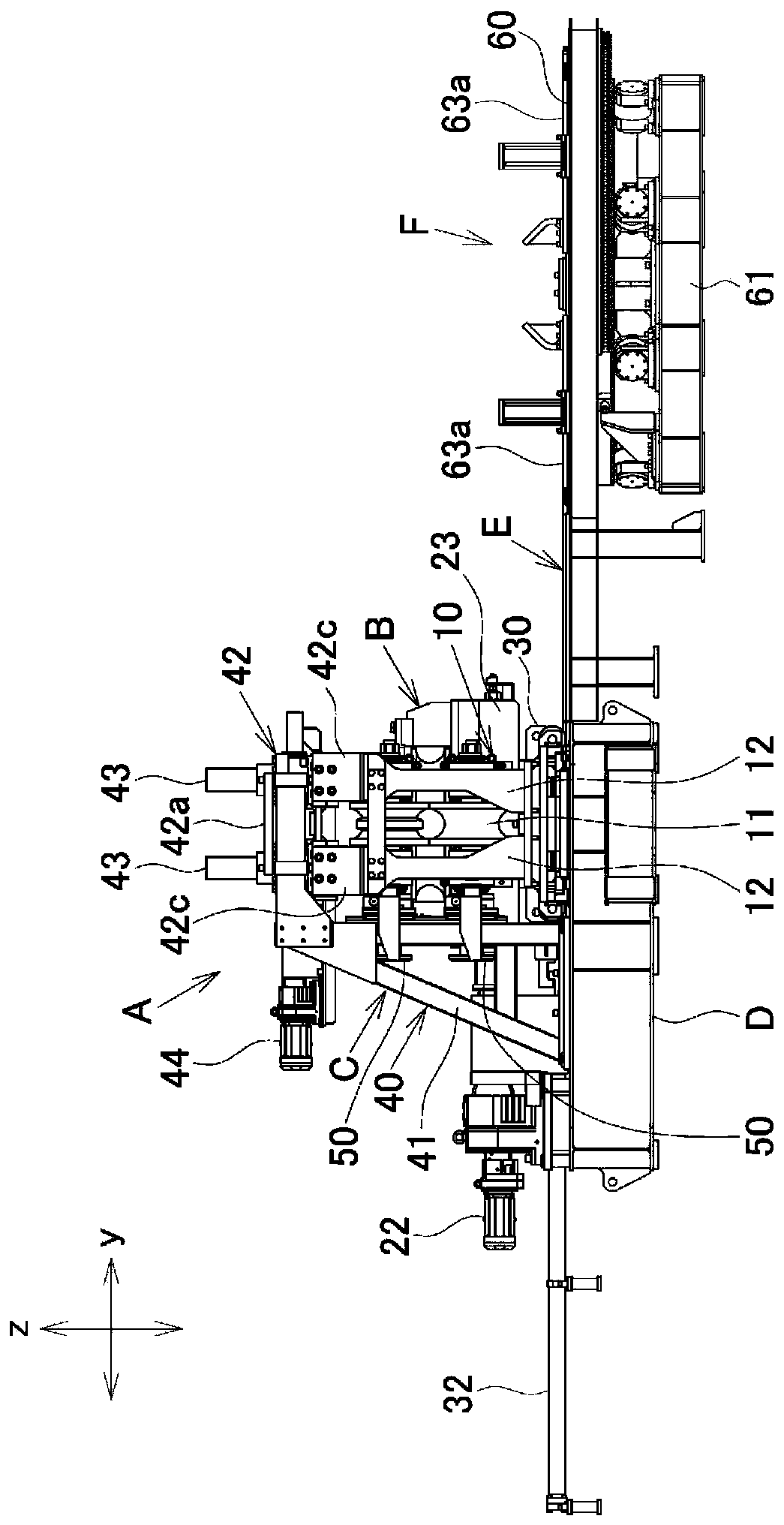
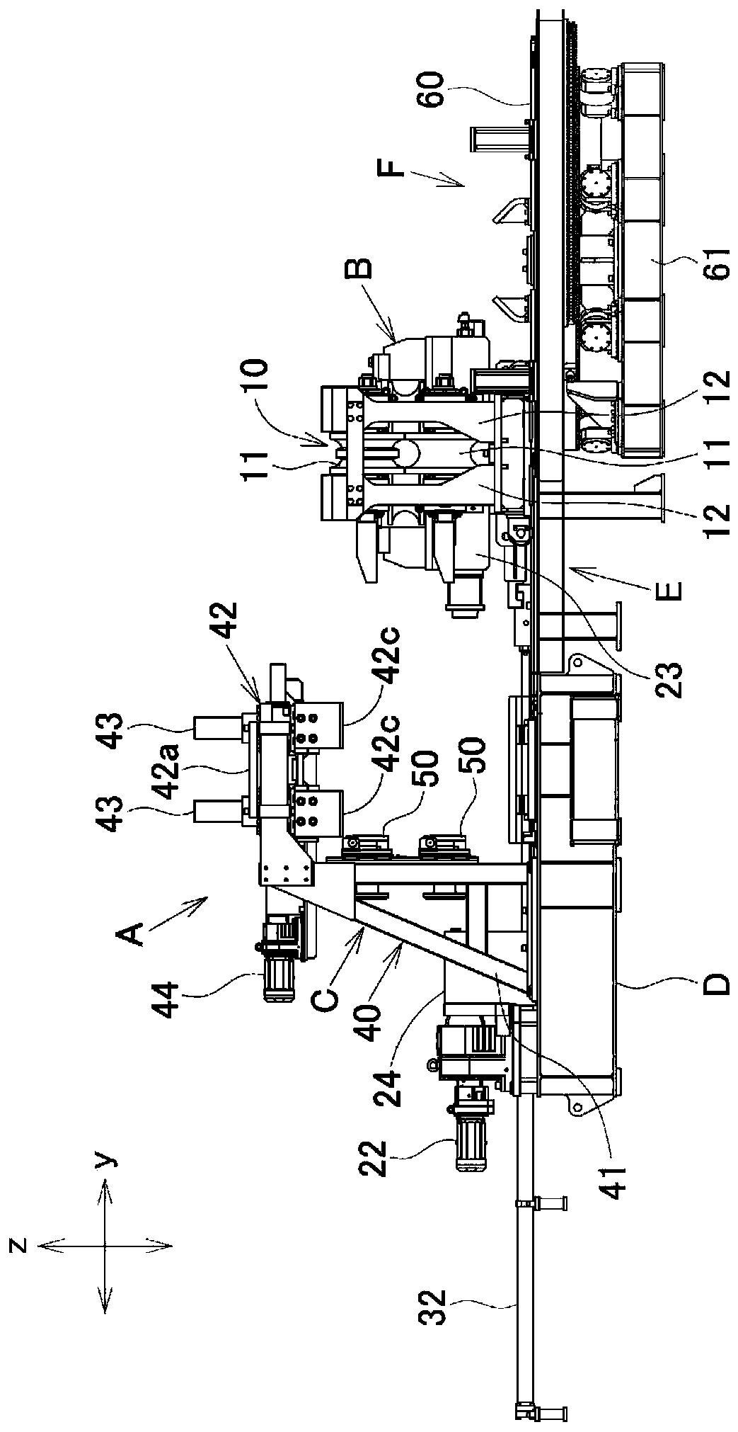
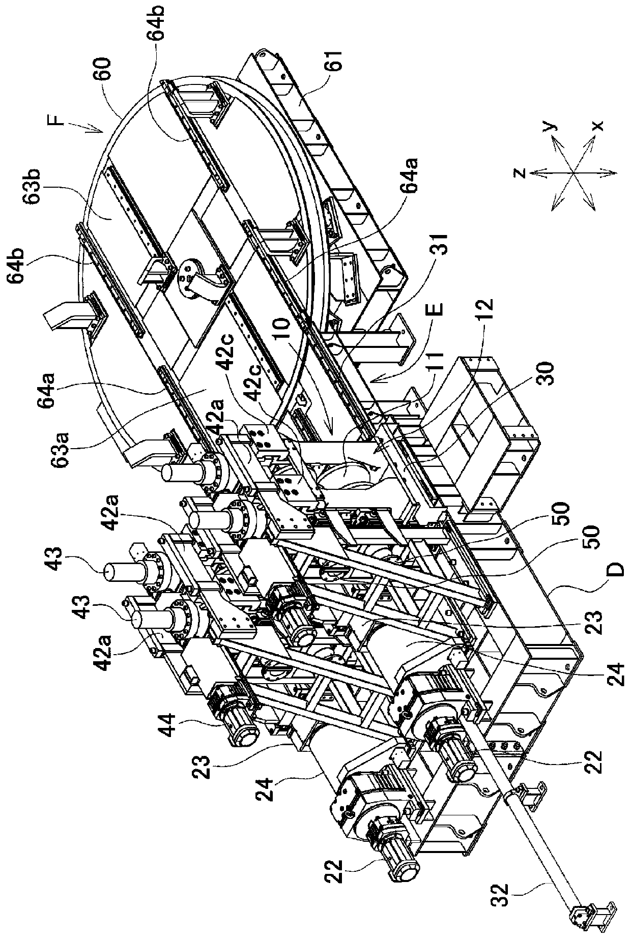
[0044] Next, an embodiment of the present invention will be described. The roll forming machine of this embodiment is a forming roll stand arranged on a production line of an electric welded steel pipe, and more specifically, the roll forming machine of this embodiment is an extrusion (hereinafter referred to as SQ) roll machine The row of fine forming (hereinafter referred to as FP) roll stands on the upstream side of the stand.

[0045] In addition, in the following description, the direction of the molding line is represented as the x direction, the horizontal direction at right angles to the x direction is represented as the y direction, the vertical direction at right angles to the x direction is represented as the z direction, and the direction of the molding line is The x direction is called the front-back direction, the y direction is called the left-right direction or the side, and the z direction is called the up-down direction. In addition, the horizontal roller in...


PUM


Abstract

The purpose of the present invention is to simply and rapidly perform replacement operations for horizontal rolls within a horizontal roll stand, including readjustment of reduction amount. To achievethis, a horizontal roll stand 10, which has an upper and lower pair of built-in horizontal rolls 11, can be retracted to one side of the forming line. A fixed stand 40 is arranged on the side of theforming line opposite from the retraction, and a reduction device 43 for imparting reduction force to the horizontal rolls 11 is provided in an overhanging part 42 for the fixed stand 40 jutting out above the forming line. The horizontal roll stand 10 has a horizontal roll housing 12 that is open at the top, and receives reduction force from the reduction device 43 via that open upper part and isretracted to the outside of the forming line leaving the reduction device 43 above the forming line. The overhanging part 42 of the fixed stand 40 is mated with the horizontal roll housing 12 of the horizontal roll stand 10 within the forming line and supports the horizontal roll housing 12.

Description

technical field [0001] The present invention relates to a roll forming machine used in the manufacture of welded pipes, and more specifically, to a roll forming machine which facilitates roll replacement work and is excellent in economical efficiency. Background technique [0002] In a production line of welded pipes such as electric welded steel pipes, in the process of passing a strip-shaped metal plate through a plurality of roll forming machines arranged along the forming line, the metal plate is formed into a tubular shape, and the butt edges are welded to form a welded pipe . In such a pipe production line, the forming rolls assembled on the roll stand in the roll forming machine are replaced according to the pipe size. Here, the exchanging operation of forming rolls is required to be performed quickly, and Patent Document 1 proposes a roll forming machine that satisfies this requirement. [0003] The roll forming machine proposed in Patent Document 1 has the followi...

Claims


Application Information

Patent Timeline
Patent Type & Authority Applications(China)
IPC IPC(8): B21D5/12B21B31/02B21B31/08B21C37/08
CPCB21D5/12B21D5/08B21D37/147B21D37/04B21C37/0818B21C37/08B21B31/02B21B31/08B21B31/20
Inventor 佐藤刚之中野智康王飞舟
Owner NAKATA MFG
Why Eureka
Try Eureka