roll forming machine

A forming machine and rolling technology, which is applied in the direction of forming tools, metal rolling stands, metal rolling mill stands, etc., can solve the problems of large-scale and high cost, and achieve the effect of simplifying the structure

Active Publication Date: 2022-07-29
NAKATA MFG
View PDF11 Cites 0 Cited by
  • Summary
  • Abstract
  • Description
  • Claims
  • Application Information

AI Technical Summary

Problems solved by technology

However, since the upper and lower horizontal rollers are in a cantilevered state through the operation side portion of the base frame when the base frame is separated, it is necessary to increase the rigidity of the base frame, which inevitably leads to an increase in size and cost. are limited to rollers with relatively small diameters such restrictions
In addition, the complication of the machine base structure due to the division of the machine base frame cannot be avoided

Method used


Image

  • roll forming machine
  • roll forming machine
  • roll forming machine

Examples


Embodiment Construction

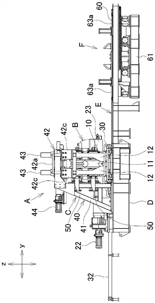
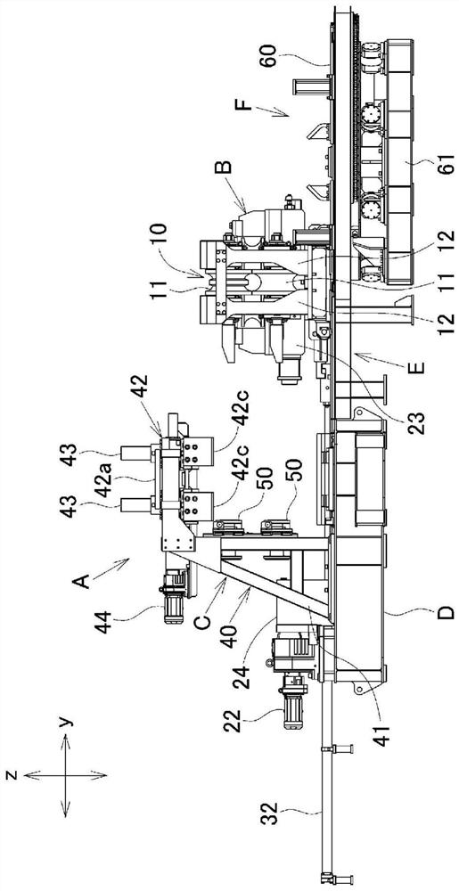
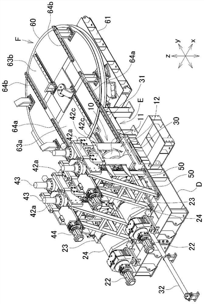
[0044] Next, an embodiment of the present invention will be described. The roll forming machine of the present embodiment is a forming roll stand arranged on a production line of electric resistance welded steel pipes, and more specifically, the roll forming machine of the present embodiment is a roll forming machine arranged on an extrusion (hereinafter referred to as SQ) A finish forming (hereinafter referred to as FP) roll stand row on the upstream side of the stand.

[0045] In addition, in the following description, the direction of the molding line is expressed as the x direction, the horizontal direction at right angles to the x direction is expressed as the y direction, the vertical direction at right angles to the x direction is expressed as the z direction, and the direction of the molding line is expressed as the z direction. The x direction is referred to as the front-rear direction, the y direction is referred to as the left-right direction or the lateral directio...


PUM


Abstract

In the present invention, the replacement operation of the horizontal rolls in the horizontal roll stand is performed simply and quickly, including the readjustment of the reduction amount. In order to realize this, a horizontal roll stand (10) incorporating a pair of upper and lower horizontal rolls (11) can be retracted to the side across the molding line. A fixed stand (40) is erected on the reverse side of the forming production line, and an overhang (42) of the fixed stand (40) that protrudes above the forming line is equipped with a pair of horizontal rollers (11). A depressing device (43) that applies a depressing force. The horizontal roll stand (10) has a horizontal roll shell (12) with an open upper part, the horizontal roll stand (10) receives a pressing force from the pressing device (43) via its open upper part, and presses the pressing down The device (43) remains on the molding line and is withdrawn from the molding line. The overhang (42) of the fixed stand (40) is matched with the horizontal roll shell (12) of the horizontal roll stand (10) in the forming production line and supports the horizontal roll shell (12).

Description

technical field [0001] The present invention relates to a roll former used for the production of a welded pipe, and more specifically, to a roll former which is easy to change the roll and has excellent economical efficiency. Background technique [0002] In a production line for welded pipes such as electric-resistance welded steel pipes, a strip-shaped metal sheet is formed into a tubular shape while the sheet metal passes through a plurality of roll formers arranged along the forming line, and the butt edges are welded to form a welded pipe . In such a pipe production line, the forming rolls assembled on the roll stand in the roll forming machine are replaced according to the pipe size. Here, the replacement work of the forming rolls requires rapidity of the replacement work, and Patent Document 1 proposes a roll former that satisfies this demand. [0003] The roll forming machine proposed in Patent Document 1 has a structure in which a horizontal roll stand in which a ...

Claims


Application Information

Patent Timeline
Patent Type & Authority Patents(China)
IPC IPC(8): B21D5/12B21B31/02B21B31/08B21C37/08
CPCB21D5/12B21D5/08B21D37/147B21D37/04B21C37/0818B21C37/08B21B31/02B21B31/08B21B31/20
Inventor 佐藤刚之中野智康王飞舟
Owner NAKATA MFG
Why Eureka
Try Eureka