Tooling and method for processing precision thin-wall bushing

A bushing and thin-walled technology, applied in the field of processing precision thin-walled bushings, can solve problems such as deformation, improper process methods, and easy deformation of pipes

Active Publication Date: 2020-07-07
AVIC BEIJING AERONAUTICAL MFG TECH RES INST
View PDF5 Cites 0 Cited by
  • Summary
  • Abstract
  • Description
  • Claims
  • Application Information

AI Technical Summary

Problems solved by technology

The high-precision machining of thin-walled bushings used in interference connections is extremely important, and improper process methods often produce waste products such as instability and deformation.
[0003] In the prior art, the processing of thin-walled bushings is formed by rolling and riveting pipes. After flaring, metal accumulation occurs under the bushing head, and the fillet at the joint between the bushing head and the rod is unstable, which cannot meet the actual use requirements, and the pipe is easy to Deformation, resulting in size out of tolerance, the head is also easy to crack, causing the product to be scrapped

Method used


Image

  • Tooling and method for processing precision thin-wall bushing
  • Tooling and method for processing precision thin-wall bushing
  • Tooling and method for processing precision thin-wall bushing

Examples


specific Embodiment 1

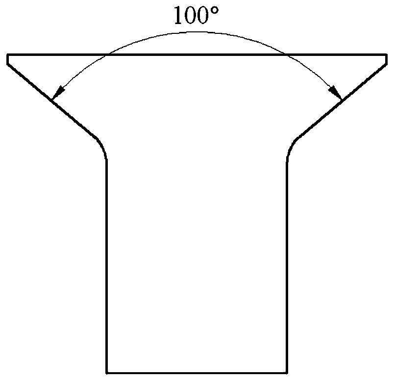
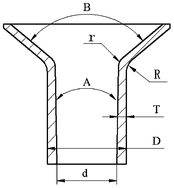
[0040] Specific embodiment 1: machining a bushing 5 with an inner diameter d of φ8mm, the taper A of the inner hole of the bushing 5 is 1.2°±0.05°, the wall thickness T of the bushing 5 is 0.20mm, and the taper length is 11mm.

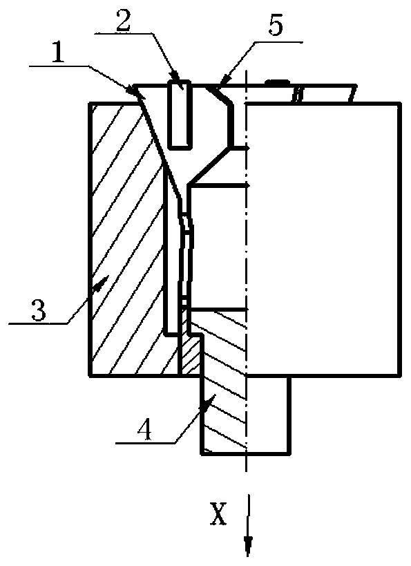
[0041] During the clamping process, the outer end surface of the head of the bushing 5 is in contact with the inner wall of the countersunk head 11 of the mounting hole, that is, figure 2 The outer end surface of the countersunk head surface B of the bushing 5 is in contact with the inner wall surface of the countersunk head 11 of the mounting hole, the outer wall surface of the inner hole of the bushing 5 is in contact with the inner wall surface of the inner hole of the clamping hole, and the outer fillet of the bushing 5 is in contact with the inner wall surface of the mounting hole. The fillet 12 in the hole is in contact, that is figure 2 The outer fillet R at the connection between the head and the tail of the bushing 5 is in contact with the i...

specific Embodiment 2

[0044] Specific embodiment 2: processing the bushing 5 whose internal diameter d of the bushing 5 is φ7.6mm, the taper A of the inner hole of the bushing 5 is 0°, that is, the straight wall bushing 5, the wall thickness T of the bushing 5 is 0.20mm, and the length is 11mm.

[0045] During the clamping process, the outer end surface of the head of the bushing 5 is in contact with the inner wall of the countersunk head 11 of the mounting hole, that is, figure 2 The outer end surface of the countersunk head surface B of the bushing 5 is in contact with the inner wall surface of the countersunk head 11 of the mounting hole, the outer wall surface of the inner hole of the bushing 5 is in contact with the inner wall surface of the inner hole of the clamping hole, and the outer fillet of the bushing 5 is in contact with the inner wall surface of the mounting hole. The fillet 12 in the hole is in contact, that is figure 2 The outer fillet R at the connection between the head and th...


PUM


Abstract

The invention relates to tooling and method for processing a precision thin-wall bushing. The tooling comprises an elastic ferrule and an outer sleeve, wherein the elastic ferrule is used for clampingthe thin-wall bushing; the outer sleeve is externally arranged on the elastic ferrule in a sleeving mode and used for clamping and guiding the elastic ferrule; and the elastic ferrule comprises an upper clamping part and a guiding part arranged at the lower end of the clamping part, a clamping hole for storing the thin-wall bushing is formed in the clamping part, the axis of the clamping hole coincides with the axis of the thin-wall bushing, the outer side surface of the clamping part is an outer tapered surface with the size gradually reduced in the X direction, a first guiding hole is formed in the guiding part, a pull rod for pulling the elastic ferrule to move in the X direction is arranged in the first guiding hole in a penetrating mode, and the upper end of the outer sleeve is provided with an inner tapered surface with the size gradually reduced in the X direction. The tooling can avoid the deformation of the bushing, and the stability and consistency of the inner wall size canbe ensured by using an integrated composite formed tool.

Description

technical field [0001] The invention relates to the technical field of machining mechanical connectors, in particular to a tool and method for machining precision thin-walled bushings. Background technique [0002] In order to meet the long-life connection requirements of aircraft, interference connection technology is usually used to improve the fatigue strength. In the interference installation process, for bolts with a diameter above 8mm to achieve a large amount of interference, the required pressing force is large, and the actual operation is difficult and cannot be satisfied. Due to the application requirements, the bushing should be used as the interference connection carrier. Using the fastening system with the inner cone bushing can greatly reduce the interference installation stroke and installation pressing force. For composite structures, it can also avoid interference connection delamination, and at the same time, it can play a role To the protective effect of e...

Claims


Application Information

Patent Timeline
Patent Type & Authority Applications(China)
IPC IPC(8): B23Q3/00B23P13/00
CPCB23P13/00B23Q3/00B23Q2703/10
Inventor 黄宏赵庆云
Owner AVIC BEIJING AERONAUTICAL MFG TECH RES INST
Why Eureka
Try Eureka