Fixing device for machining end face position holes of supporting frame

A technology of fixing equipment and support frame, which is applied in metal processing equipment, positioning devices, metal processing mechanical parts, etc., can solve the problems of time-consuming and laborious, long time for disassembling and assembling workpieces, and reducing workpiece processing accuracy.

Inactive Publication Date: 2020-07-07
天津市臣涛精密机械设备有限公司
View PDF0 Cites 0 Cited by
  • Summary
  • Abstract
  • Description
  • Claims
  • Application Information

AI Technical Summary

Problems solved by technology

This method is time-consuming and laborious, and it takes a long time to disassemble and assemble the workpiece, which affects the overall production pro

Method used


Image

  • Fixing device for machining end face position holes of supporting frame
  • Fixing device for machining end face position holes of supporting frame
  • Fixing device for machining end face position holes of supporting frame

Examples


Embodiment Construction

[0018] The embodiments of the present invention will be described in detail below in conjunction with the accompanying drawings; it should be noted that the embodiments are illustrative, not restrictive, and cannot limit the protection scope of the present invention.

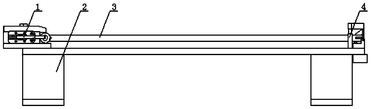
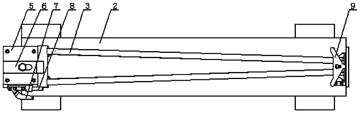
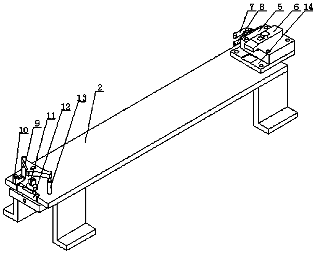
[0019] A fixing device for machining end face position holes of a support frame, comprising a base 2 , a left positioning mechanism 1 and a right positioning mechanism 4 .

[0020] The left positioning mechanism includes a fixed block 5, an upper pressure plate 6, a quick-press wrench 7 and a positioning bar 8. The left side of the upper surface of the base is equipped with a fixed block, and the right side of the fixed block forms a positioning bar for placing workpieces. Slot 14. An upper pressing plate is installed on the upper surface of the fixed block, and a long hole is made on the upper pressing plate, and a top wire is installed in the long hole. above the slot. A quick-press wrench is installed on th...


PUM


Abstract

The invention relates to a fixing device for machining end face position holes of a supporting frame. The fixing device comprises a base, a left side positioning mechanism and a right side positioningmechanism. The fixing device for machining the end face position holes of the supporting frame is scientific in design, reasonable in structure, convenient to use, high in specificity and low in manufacturing cost, and by means of the fixing device, the working process can be simplified, the assembling and clamping time can be shortened, the work efficiency can be improved, and the product quality can be guaranteed.

Description

technical field [0001] The invention relates to a positioning tool in the technical field of support frame production, in particular to a fixing device for processing end surface position holes of a support frame. Background technique [0002] The support frame in the solar generator set has the characteristics of large volume, heavy weight, long length, and asymmetrical left and right ends. During the production process of the support frame, the position holes on the left and right end surfaces need to be milled. At present, the more common way is to fix the workpiece, first mill the position hole on one side of the end face, then remove the workpiece, adjust the direction, fix it again, and then mill the position hole on the other side end face. This method is time-consuming and labor-intensive, and it takes a long time to disassemble and assemble the workpiece, which affects the overall production progress. Moreover, repeated clamping will inevitably increase the clampin...

Claims


Application Information

Patent Timeline
IPC IPC(8): B23Q3/06
CPCB23Q3/062
Inventor 崔雅臣张涛崔超崔越崔文来崔建涛李绍功李绍德崔雅海
Owner 天津市臣涛精密机械设备有限公司
Why Eureka
Try Eureka