Lathe clamp for machining thin-wall end cover parts

A vehicle fixture and end cap technology, which is used in metal processing machinery parts, manufacturing tools, metal processing equipment, etc., can solve the problem of hydraulic three-jaw chuck clamping deformation that cannot meet design requirements and other problems

Pending Publication Date: 2020-07-07
WUXI WEIFU PRECISION MACHINERY MFG
View PDF0 Cites 0 Cited by
  • Summary
  • Abstract
  • Description
  • Claims
  • Application Information

AI Technical Summary

Problems solved by technology

[0005] In view of the above problems, the present invention provides a turning fixture for processing thin-walled end cap parts. The main purpose of the turning fixture is to improve the problem that the clamping deformation of the hydraulic three

Method used


Image

  • Lathe clamp for machining thin-wall end cover parts
  • Lathe clamp for machining thin-wall end cover parts

Examples


Embodiment Construction

[0017] The specific embodiments of the present invention will be further described below in conjunction with the accompanying drawings.

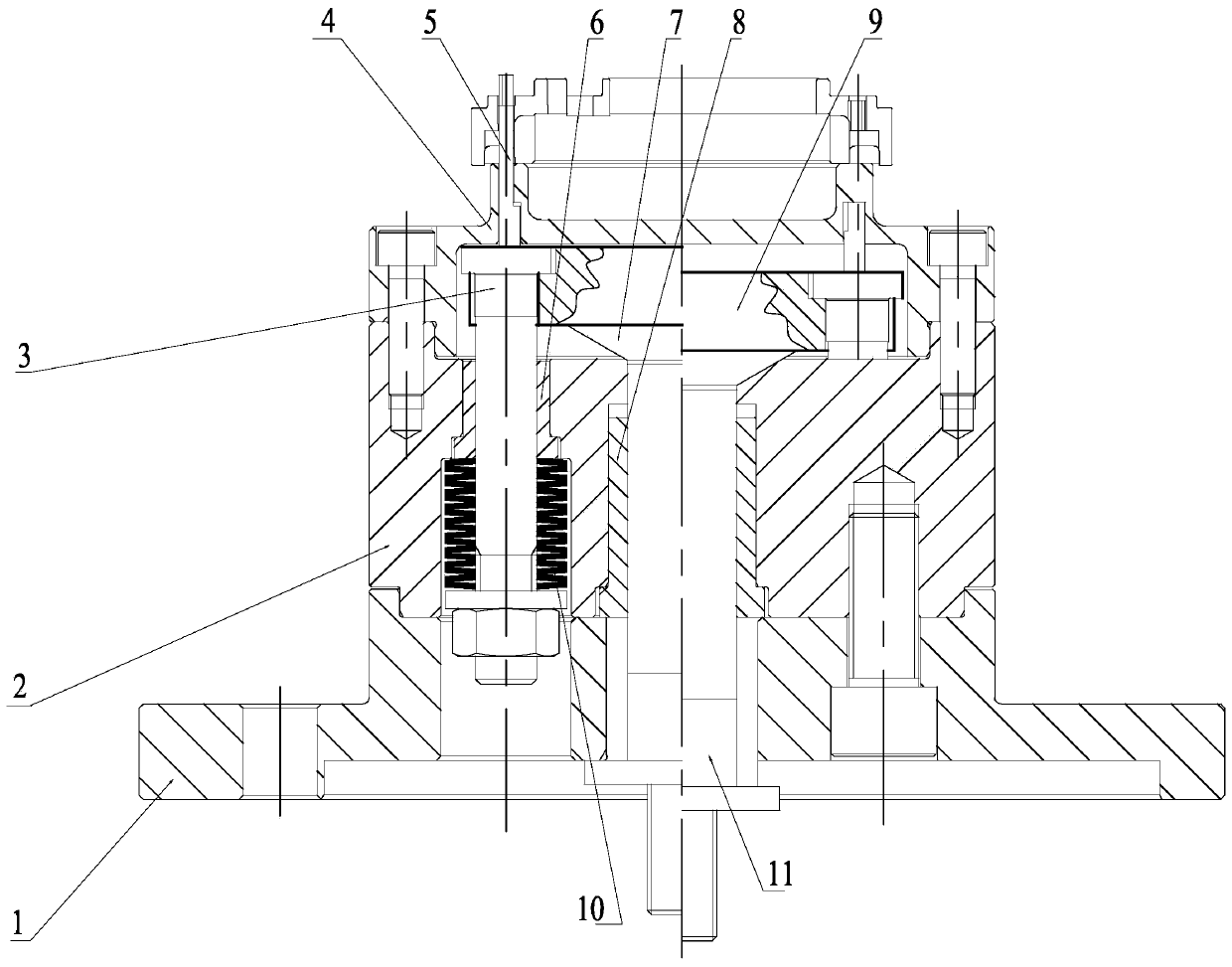
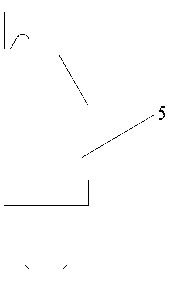
[0018] figure 1 , 2 Among them, it includes the lower connecting body 1, the intermediate body 2, the guide post 3, the clip body 4, the pressure block 5, the first guide sleeve 6, the first push rod 7, the second guide sleeve 8, the top plate 9, the disc spring 10, The second push rod 11 etc.

[0019] Such as figure 1 , 2 As shown, the present invention is a vehicle fixture for processing thin-walled end cap parts, including a mounting base plate 1, an intermediate body 2 is mounted on the top surface of the mounting base plate 1, and a clamping body 4 is mounted on the top surface of the intermediate body 2; the clamping body 4 A plurality of briquetting blocks 5 are evenly distributed along the upper circumference, and each briquetting block 5 passes through the clamp body 4 and then connects with the built-in stretching mechanism of ...


PUM


Abstract

The invention belongs to the technical field of clamp equipment, and relates to a lathe clamp for machining thin-wall end cover parts. The lathe clamp comprises a mounting bottom plate, an intermediate is mounted on the top face of the mounting bottom plate, and a clamp body is mounted on the top face of the intermediate. Multiple pressing blocks are evenly distributed on the clamp body along thecircumference, and each pressing block penetrates through the clamp body and then is connected with a stretching mechanism in the intermediate and driven by the stretching mechanism to axially move. An elastic mechanism is further arranged on the stretching mechanism, so that the pressing blocks are in the state of clamping the workpieces in a natural state. The lathe clamp mainly aims at solvingthe problem that the design requirements cannot be met due to clamping deformation of a three-jaw chuck, a lathe spindle taper hole and a part hollowed-out structure are utilized, a positioning mechanism is ingeniously arranged, and the purposes that a numerical control lathe is provided with an oil cylinder, rapid clamping and positioning can be achieved, and deformation can be greatly reduced are achieved.

Description

technical field [0001] The invention belongs to the technical field of fixture equipment, and relates to a vehicle fixture for processing thin-walled end cap parts. Background technique [0002] The gear pump bearing gland is a cast aluminum thin-walled part, and there are multiple through grooves and inner grooves on the part, which further thins the joint. In the process of mass production of lathe processing, it is mainly limited by the following factors: First, conventional lathes can only use hydraulic three-jaw chucks for clamping and production, which brings obvious problems. Faced with thin-walled aluminum parts, and For such parts with hollow structure and no rib support, the uncontrollable deformation will make the processing unable to meet the design requirements. Regardless of inner support or outer support, it will lead to the phenomenon of parts being sent away and out of tolerance. [0003] Second, the processing nature of the lathe and the particularity of ...

Claims


Application Information

Patent Timeline
IPC IPC(8): B23Q3/12
CPCB23Q3/12B23Q2703/10
Inventor 邢倞余学军
Owner WUXI WEIFU PRECISION MACHINERY MFG
Why Eureka
Try Eureka