Injection molding mechanism for fast blanking and operation method thereof

A rapid and injection molding technology, applied in the field of mold forming, can solve problems that affect product quality, increase production costs, and safety hazards

Pending Publication Date: 2020-07-07
林冰莺
View PDF0 Cites 7 Cited by
  • Summary
  • Abstract
  • Description
  • Claims
  • Application Information

AI Technical Summary

Problems solved by technology

[0004] The purpose of the present invention is to solve the problem in the prior art that the injection molding mechanism is not easy to demould, which leads to a slow blanking rate of the forming mold. At the same time, the temperature in the mold cavity is too high, which leads to the slow shaping of the internal plastic parts, which is easy to remove during the removal process. The problem of pulling deformation occurs, which seriously affects the product quality, resulting in a large number of returned

Method used


Image

  • Injection molding mechanism for fast blanking and operation method thereof
  • Injection molding mechanism for fast blanking and operation method thereof
  • Injection molding mechanism for fast blanking and operation method thereof

Examples


Embodiment Construction

[0033] The technical solutions of the present invention will be clearly and completely described below in conjunction with the embodiments. Apparently, the described embodiments are only some of the embodiments of the present invention, not all of them. Based on the embodiments of the present invention, all other embodiments obtained by persons of ordinary skill in the art without creative efforts fall within the protection scope of the present invention.

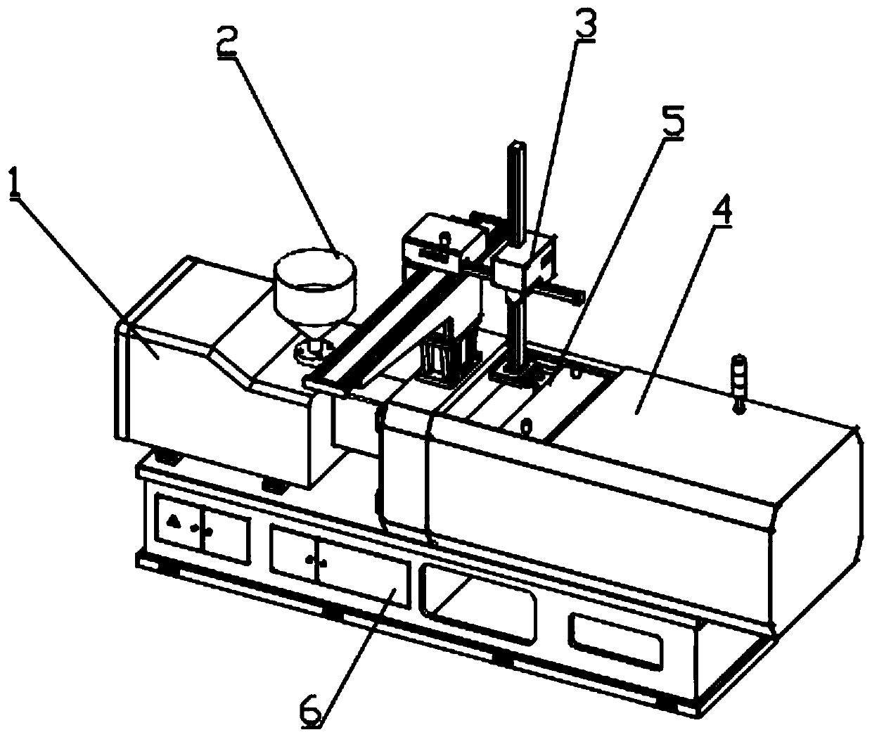
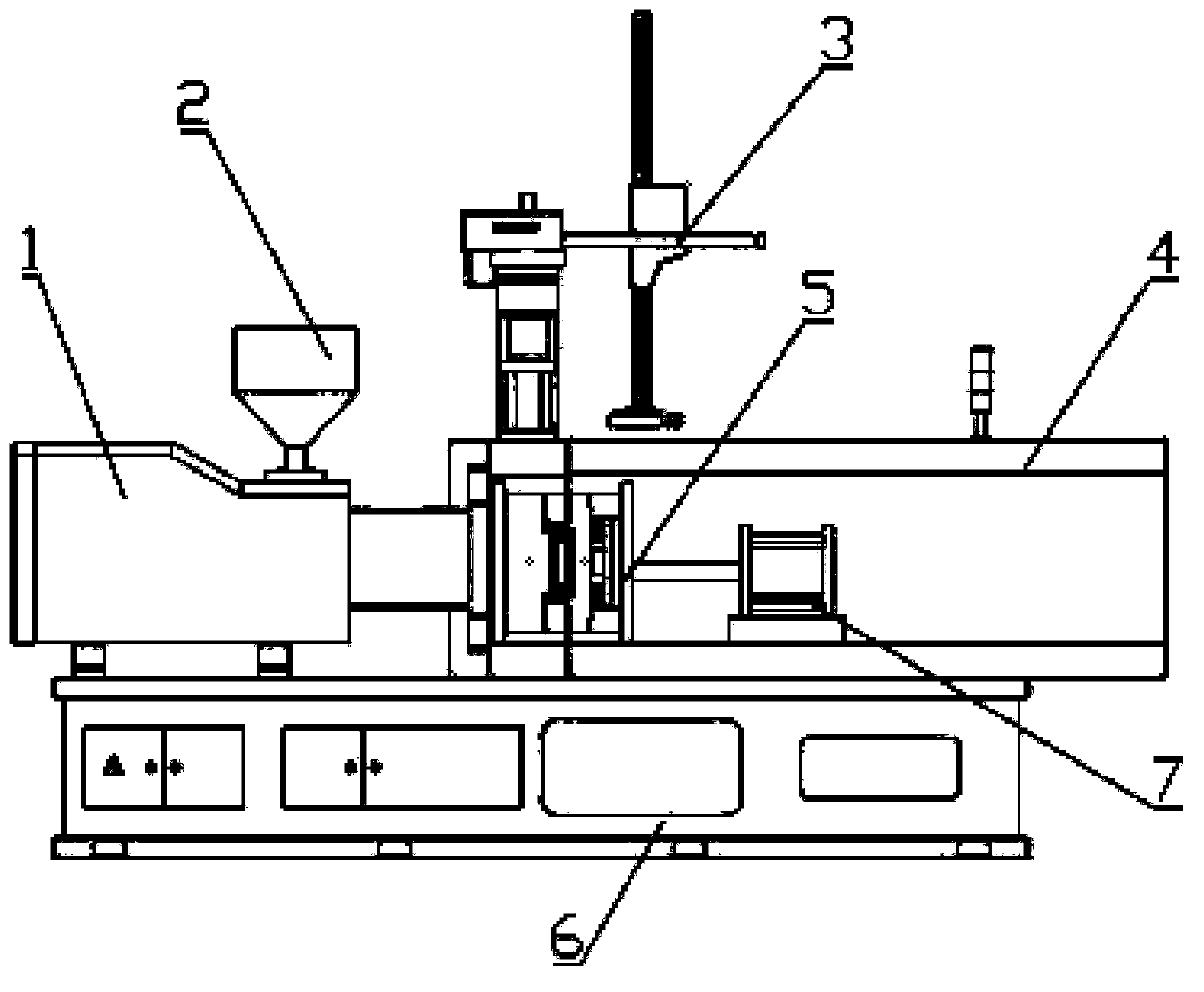
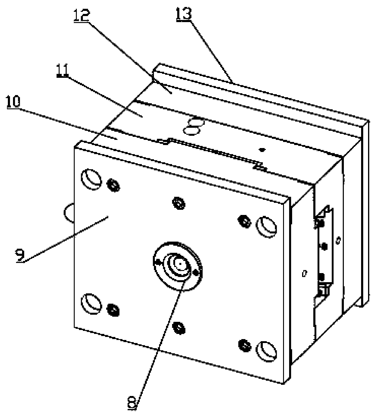
[0034] see Figure 1-9 As shown, a rapid blanking injection molding mechanism includes a feeding box 1, an injection molding box 4 and an injection molding device 5, the feeding box 1 is installed on the top side of the base 6, and the injection molding box 4 is installed on the top of the base 6 On the other side of the surface, a feeding funnel 2 is arranged on the top surface of the feeding box 1, and an injection molding device 5 is arranged in the injection molding box 4. The feeding end on one side of the injection mo...


PUM


Abstract

The invention discloses an injection molding mechanism for fast blanking. The injection molding mechanism comprises a feeding box, an injection molding box and an injection molding device, the feedingbox is arranged on one side of the top surface of a base, the injection molding box is arranged on the other side of the top surface of the base, a feeding funnel is arranged on the top surface of the feeding box, the feeding end on one side of the injection molding device communicates with the feeding box, and the other side of the injection molding device is connected with the output end of a hydraulic cylinder; the hydraulic cylinder is installed on the inner bottom surface of the injection molding box; and a fixed die fixing plate is arranged on the inner wall of the injection molding box, a fixed die is arranged on the side wall, far away from the feeding box, of the fixed die fixing plate, one side of a movable die fixing plate is connected with the output end of the hydraulic cylinder, an ejection plate is arranged on the other side of the movable die fixing plate, a movable die matched with a fixed die is arranged on the other side of the ejection plate, a guide rod is arranged on the side wall, close to the movable die, of the fixed die, and an ejection mechanism is arranged in the ejection plate. The injection molding mechanism has the advantages that the blanking rate is greatly improved, uniform die cooling can be realized, the forming efficiency is greatly improved, and automatic material taking is achieved.

Description

technical field [0001] The invention belongs to the technical field of mold forming, and relates to an injection molding mechanism and an operation method thereof, in particular to an injection molding mechanism for rapid blanking and an operation method thereof. Background technique [0002] Under the action of external force, the mold makes the blank into a tool with a specific shape and size. It is widely used in blanking, die forging, cold heading, extrusion, powder metallurgy parts pressing, pressure casting, and engineering plastics, rubber, ceramics, etc. In the forming process of compression molding or injection molding of products. [0003] In the prior art, the injection molding mechanism is not easy to demould, which leads to a slow blanking rate of the molding mold. At the same time, the temperature in the mold cavity is too high, which leads to the slow shaping of the internal plastic parts, and the problem of pulling and deformation is prone to occur during the...

Claims


Application Information

Patent Timeline
IPC IPC(8): B29C45/03B29C45/40B29C45/26B29C45/73B29C45/42B29C45/17
CPCB29C45/03B29C45/1769B29C45/26B29C45/401B29C45/42B29C45/7312B29C45/7331B29C2045/177B29C2045/4266B29C2045/7318
Inventor 林冰莺
Owner 林冰莺
Why Eureka
Try Eureka