
Automatic feeding and discharging mechanism and Mini LED screen chip testing device

A technology of automatic loading and unloading and chip testing, which is applied in the direction of conveyor objects, transportation and packaging, instruments, etc., which can solve the problems of inaccessible probes, inaccurate test points of Mini LED screen chips, poor stability, etc.

Inactive Publication Date: 2020-07-07
苏州润弘安创自动化科技有限公司
View PDF8 Cites 3 Cited by
  • Summary
  • Abstract
  • Description
  • Claims
  • Application Information

AI Technical Summary

Problems solved by technology

[0004] Traditional testing equipment relies on operators to manually carry Mini LED screen chips to realize loading and unloading of Mini LED screen chips. The labor intensity of operators is relatively high, and the speed of loading and unloading is slow, which affects work efficiency.
At the same time, when testing the Mini LED screen chip, it is necessary to manually operate the probe to touch the contact point of the Mini LED screen chip. There is a problem that the probe cannot touch the contact point of the Mini LED screen chip. Inaccurate, poor stability, and affected by human uncertain factors, the test accuracy is low

Method used


Image

  • Automatic feeding and discharging mechanism and Mini LED screen chip testing device
  • Automatic feeding and discharging mechanism and Mini LED screen chip testing device
  • Automatic feeding and discharging mechanism and Mini LED screen chip testing device

Examples


Embodiment Construction

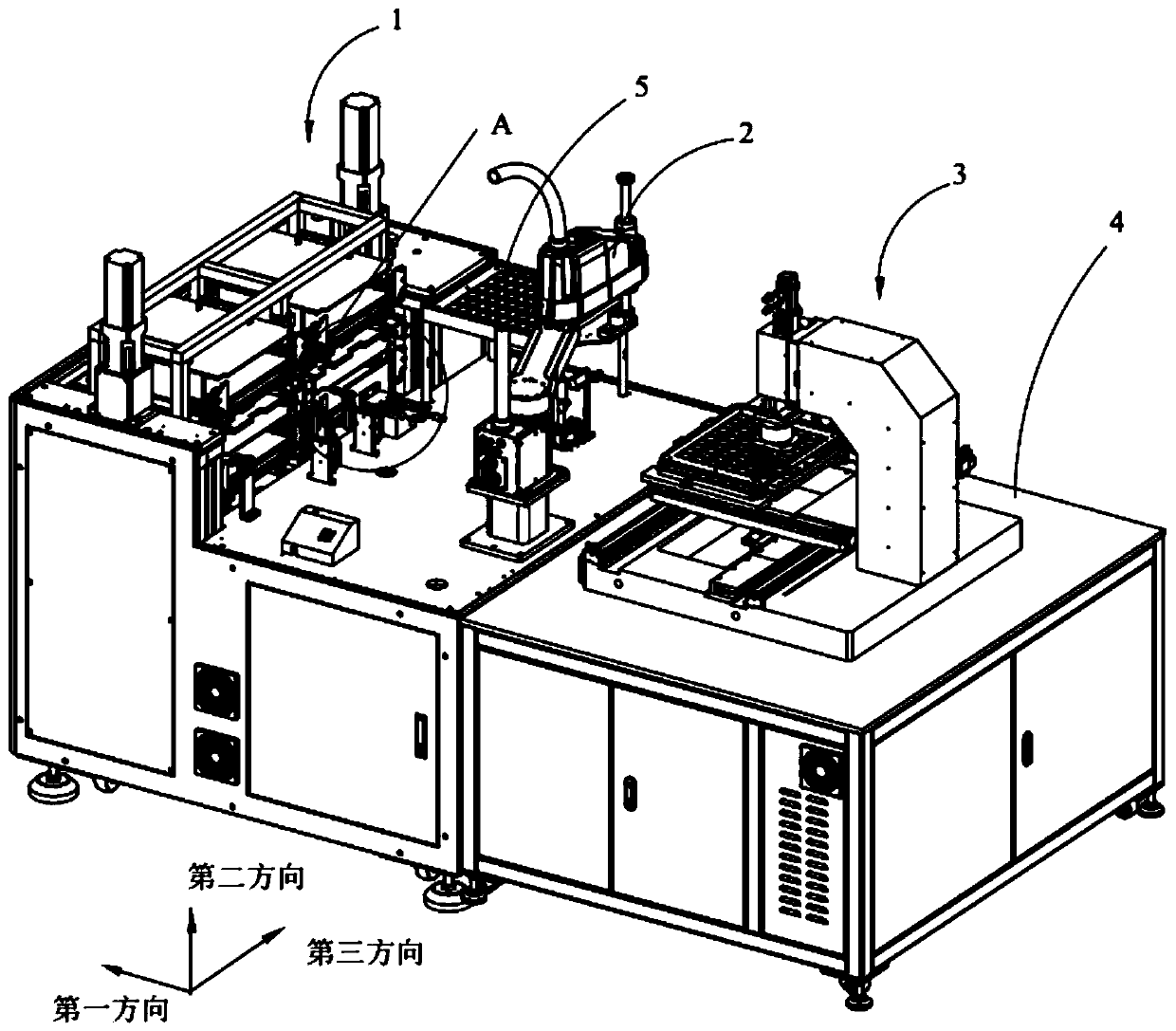
[0058]In order to make the technical problems solved by the present invention, the technical solutions adopted and the technical effects achieved clearer, the technical solutions of the embodiments of the present invention will be further described in detail below in conjunction with the accompanying drawings. Obviously, the described embodiments are only the technical solutions of the present invention. Some, but not all, embodiments. Based on the embodiments of the present invention, all other embodiments obtained by those skilled in the art without creative efforts fall within the protection scope of the present invention.

[0059] In the description of the present invention, unless otherwise clearly specified and limited, the terms "connected", "connected" and "fixed" should be understood in a broad sense, for example, it can be a fixed connection, a detachable connection, or an integrated ; It can be a mechanical connection or an electrical connection; it can be a direct ...


PUM


Abstract

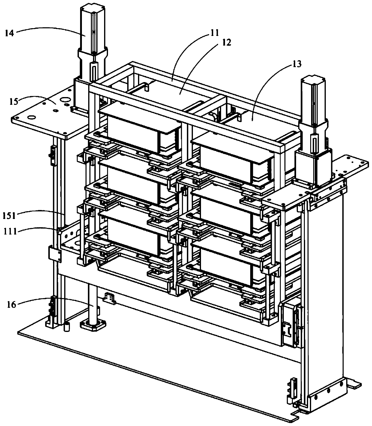
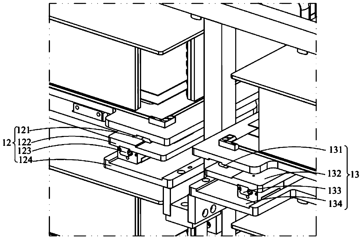
The invention belongs to the technical field of Mini LED screen chip testing, and discloses an automatic feeding and discharging mechanism and a Mini LED screen chip testing device. The automatic feeding and discharging mechanism comprises a frame, a first drawer box, a second drawer box and a lifting driving source; the first drawer box is arranged on the frame in a sliding mode in the first direction, and the first drawer box is used for bearing a to-be-tested workpiece; the second drawer box is arranged on the frame in a sliding mode in the first direction and is parallel to the first drawer box, the second drawer box is used for bearing a tested finished workpiece, and the conveying direction of the finished workpiece is opposite to the conveying direction of the to-be-tested workpiece; and the output end of the lifting driving source is connected to the frame, the lifting driving source can drive the frame to move in the second direction, and the first direction and the second direction are perpendicular to each other. According to the automatic feeding and discharging mechanism, under the combined action of the lifting driving source, the frame, the first drawer box and the second drawer box, the labor burden is relieved, and the production efficiency is effectively improved.

Description

technical field [0001] The invention relates to the technical field of Mini LED screen chip testing, in particular to an automatic loading and unloading mechanism and a Mini LED screen chip testing device. Background technique [0002] As the public pursues ultra-clear display, display technology requires higher contrast. Mini LED, known as next-generation display technology, has become an active field for manufacturers. , color reproduction, and energy saving are far superior to today's LCD displays, and can even compete with AMO LEDs while keeping production costs in check. Thanks to the vastly increased number of LEDs used for panel backlighting, the new technology could greatly improve the HDR performance of LCD screens. [0003] Mini LED screen chips are precision components of new display screen products. With the vigorous development of the electronic product manufacturing industry, production units are considering the quality of Mini LED screen chips and have higher...

Claims


Application Information

Patent Timeline
IPC IPC(8): B65G47/74B65G47/90G09G3/00
CPCB65G47/74B65G47/902G09G3/006
Inventor 徐文飞刘红燕周宇王海涛刘国举李陆平
Owner 苏州润弘安创自动化科技有限公司
Learn More