Eureka AIR delivers breakthrough ideas for toughest innovation challenges, trusted by R&D personnel around the world.

Laser radar transmitting system

A launch system, laser radar technology, applied in the field of optics, can solve the problems of high cost, large volume, inconvenient use, etc.

Active Publication Date: 2020-07-07
SUTENG INNOVATION TECH CO LTD
View PDF7 Cites 1 Cited by
  • Summary
  • Abstract
  • Description
  • Claims
  • Application Information

AI Technical Summary

Problems solved by technology

[0004] However, by expanding the diameter of the launch port or increasing the focal length of the launch system, the cost is high, the volume is large, and it is inconvenient to use.

Method used


Image

  • Laser radar transmitting system
  • Laser radar transmitting system
  • Laser radar transmitting system

Examples


Embodiment Construction

[0032] In order to make the purpose, technical solution and advantages of the present application clearer, the present application will be further described in detail below in conjunction with the accompanying drawings and embodiments. It should be understood that the specific embodiments described here are only used to explain the present application, and are not intended to limit the present application.

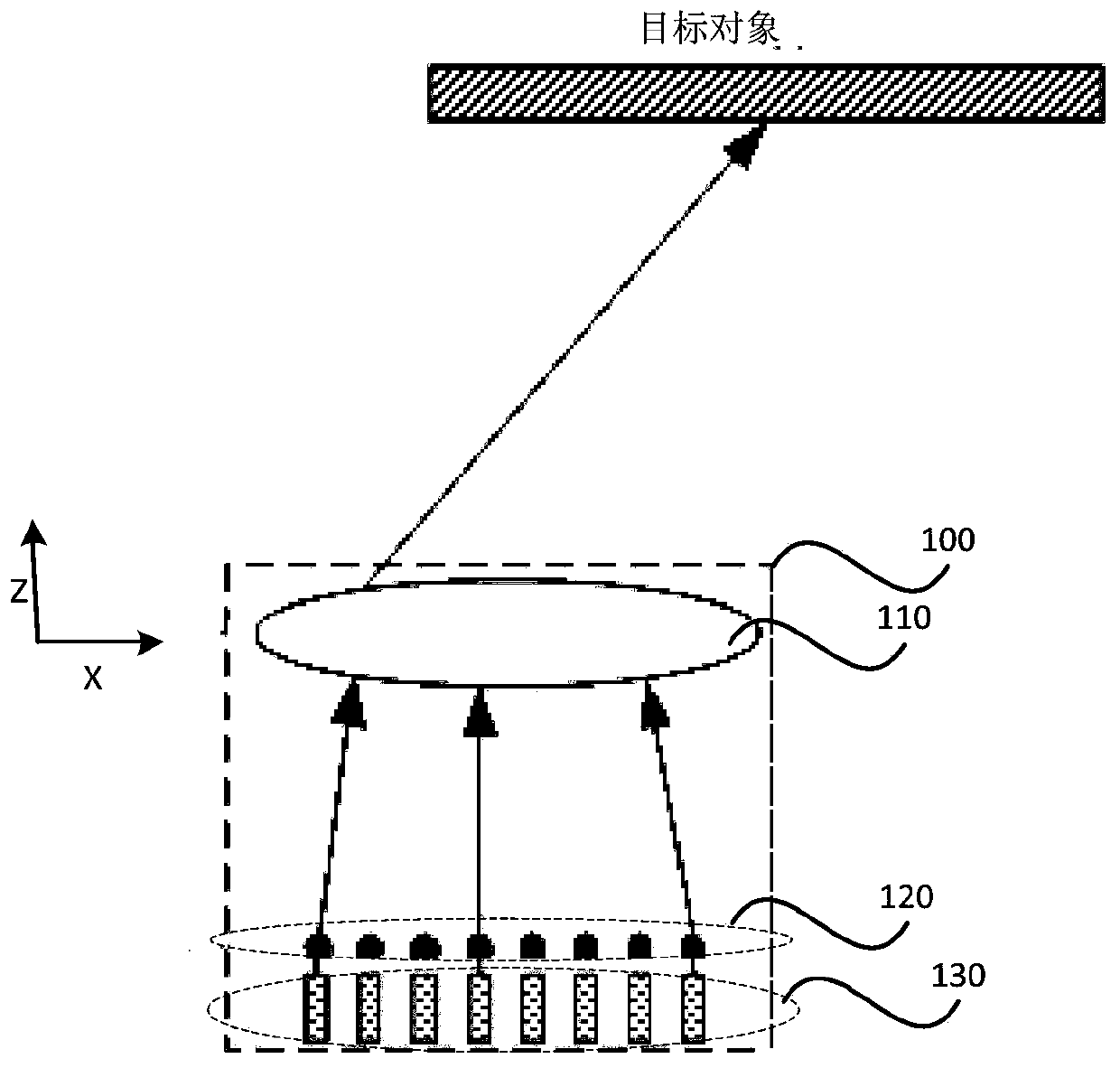
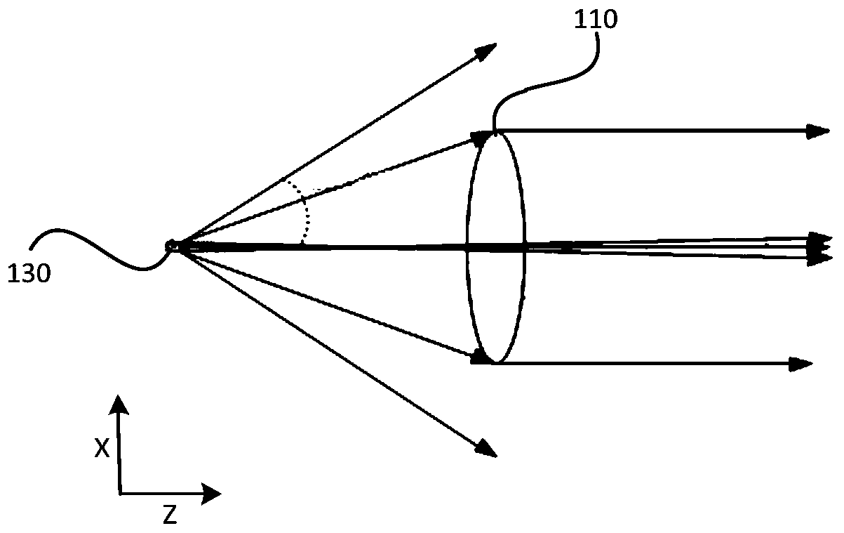
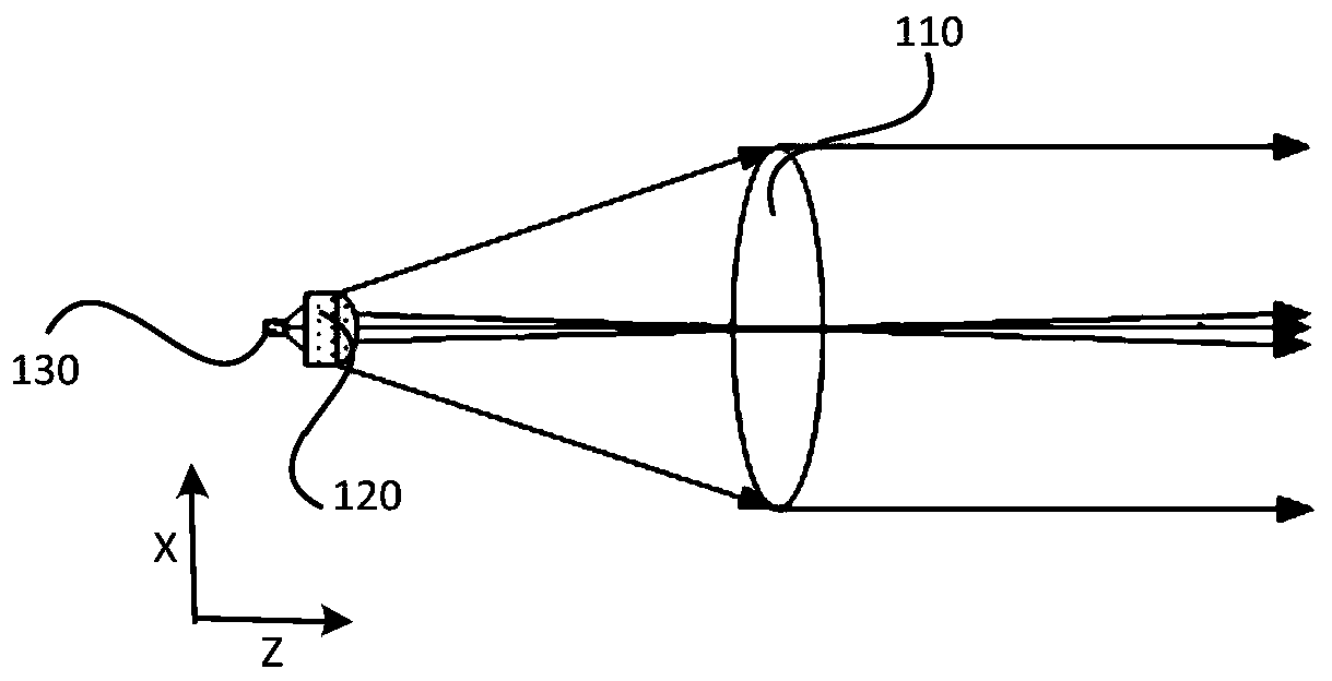
[0033] figure 1 A schematic structural diagram of a lidar transmitting system provided for an embodiment. The system 100 includes: a transmitting end optical unit 110, a Fast Axis Collimator (FAC) array 120 and a laser diode LD transmitting array 130, and the FAC array 120 is used to fast-track the laser beam emitted by the LD transmitting array 130. Axial correction. When the laser beam emitted by the LD emitting array 130 passes through the FAC array 120 , the divergence angle of the laser beam in the direction of the fast axis is corrected, and then the laser beam is ...


PUM


Abstract

The invention relates to a laser radar transmitting system, which comprises an emission end optical unit, a fast axis collimation FAC array and a laser diode LD emission array, and is characterized inthat the FAC array is used for carrying out fast axis direction correction on laser beams emitted by the LD emission array; when a laser beam emitted by the LD emission array passes through the FAC array, the divergence angle of the laser beam in the fast axis direction is corrected, and then the laser beam is emitted through the emission end optical unit. By adopting the laser radar transmittingsystem, the size is greatly reduced, and the cost is also greatly reduced.

Description

technical field [0001] The present application relates to the field of optical technology, in particular to a laser radar emission system. Background technique [0002] With the rapid development of optical technology and communication technology, lidar technology has developed rapidly. Because lidar can detect the position and speed of the target object by emitting laser beams and receiving the laser beams reflected from the target object, it is widely used in target detection and other fields. [0003] At present, in order to make the laser beam emitted by the lidar emit more efficiently and reduce energy loss, a common practice is to expand the aperture of the emission end or increase the focal length of the emission system to achieve higher energy utilization. [0004] However, by enlarging the diameter of the launch port or increasing the focal length of the launch system, the cost is high, the volume is large, and it is inconvenient to use. Contents of the invention...

Claims


Application Information

Patent Timeline
Patent Type & Authority Applications(China)
IPC IPC(8): G01S17/02G01S7/484G01S7/491
CPCG01S17/02G01S7/484G01S7/4911
Inventor 刘波
Owner SUTENG INNOVATION TECH CO LTD
Why Eureka
Eureka Blog
Learn More