Efficient disinfecting and killing conveying line

A transmission line, high-efficiency technology, applied in the field of high-efficiency disinfection transmission line, can solve the problems of low disinfection efficiency, low efficiency, penetration function and life expectancy, etc., to achieve improved disinfection transmission efficiency, high ultraviolet intensity, and path controllable effect

Inactive Publication Date: 2020-07-10
ZHEJIANG GINHENRY NEW TECH DEV
View PDF14 Cites 5 Cited by
  • Summary
  • Abstract
  • Description
  • Claims
  • Application Information

AI Technical Summary

Problems solved by technology

However, it needs to travel a long path in the disinfection box when transporting the above-mentioned disinfecting targets, the efficiency is low, and the energy consumed by the device driving is converted into the disinfecting effect. The penetration of objects (such as masks, disposable bamboo chopsticks, etc.) will affect their function and lifespan

Method used


Image

  • Efficient disinfecting and killing conveying line
  • Efficient disinfecting and killing conveying line
  • Efficient disinfecting and killing conveying line

Examples


Embodiment 1

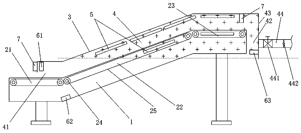
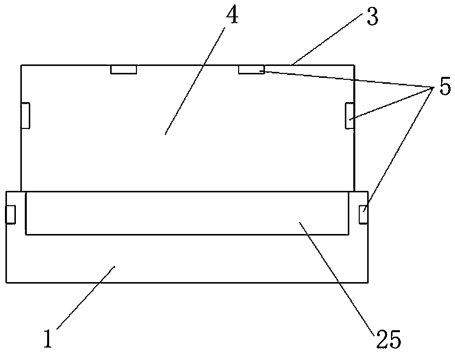
[0030] Such as figure 1 , 2 A high-efficiency disinfecting conveyor line shown in . The support in this embodiment includes a vertical stand arranged from bottom to top and a frame with a concave cross-section installed above the vertical stand and arranged according to the extended shape of the conveying line, and its wall surface is a closed wall surface. The conveyor line has a horizontally arranged feed section 21 and a discharge section 23 positioned at both ends of the conveying direction. The material section 21 is connected to the upwardly inclined connecting section 22 of the discharging section 23, so that the sterilized target material fed from the upstream is formed on this conveying line, and after entering the feeding section 21, it is lifted to the discharging section 23 through the connecting section 22 sent horizontally. The bracket 1 and the housing 3 enclose to form the accommodation chamber 4, the housing 3 and the feeding section 21 enclose to form the ...

Embodiment 2

[0042] Such as Figure 4 As shown, the embodiment described in the second embodiment is similar to the first embodiment, the difference is that:

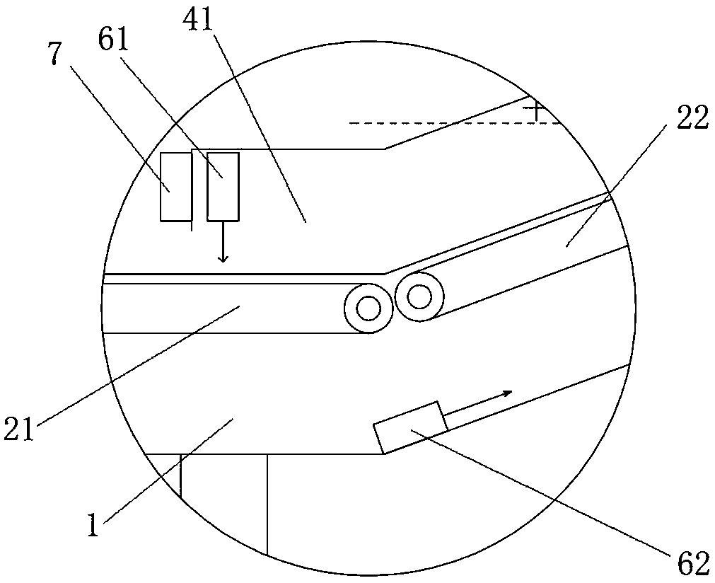
[0043] In this embodiment, it also includes a first air curtain machine 61 and a second air curtain machine 62 located at the entrance 41, the first air curtain machine 61 is located at the housing 3 at the entrance 41 and points to the conveying line below, the first There is a 10° angle between the plane where the air supply direction of the tuyere of the air curtain machine 61 is located and the vertical plane perpendicular to the conveying line, which is biased towards the direction of the accommodation chamber 4, and the angle realizes the air supply obliquely to the conveying line at the entrance, and further When encountering a certain obstacle on the surface of the conveying line, it presents a reflection-shaped air path toward the connecting section 22 in the housing chamber, thereby further preventing the downward loss of oz...

Embodiment 3

[0045] Such as Figure 5 As shown, the specific implementation manner of embodiment three is similar to embodiment one, and its difference is:

[0046] In this embodiment, the connecting section 22 provided between the feeding section 21 and the discharging section 23 has a trapezoidal structure starting from the rear side of the feeding section 21, which is inclined-horizontal-downward and connects the discharging section 23. Under this structure, the formed accommodating chamber 4 and the ozone concentration line therein have a better ability to maintain.


PUM


Abstract

The invention aims to provide an efficient disinfecting and killing conveying line which is used for solving the problems existing in the prior art. The efficient disinfecting and killing conveying line comprises a support, a conveying line body located on the support, a shell covering the conveying line body and an ultraviolet irradiation device located in the shell and connected with an ozone concentration sensor, wherein the conveying line body is provided with a feeding section and a discharging section which are located at the two ends of the conveying direction of the conveying line body; the feeding section and the discharging section are connected through a connecting section which is located between the feeding section and the discharging section and provided with at least one inclination angle; a containing cavity is defined by the support and the shell. An inlet of the containing cavity is defined by the shell and the feeding section; and an outlet of the containing cavity is defined by the shell and the discharging section. By means of the efficient disinfecting and killing conveying line, rapid conveying in a short path can be achieved, disinfecting and killing objectssuch as masks, disposable chopsticks and tableware can be better and more effectively disinfected and killed through rapid conveying, the operation process of the whole device can be dynamically adjusted, and energy consumption is low.

Description

technical field [0001] The invention relates to the technical field of disinfection and sterilization equipment, in particular to a high-efficiency disinfection transmission line. Background technique [0002] Due to manual operations and multiple processes in the production process of masks, disposable chopsticks, and tableware, harmful objects such as bacteria will inevitably exist on the surface. Therefore, disinfection and dust removal are required before final packaging to reduce risks during use. Now the production is streamlined, and the disinfection is carried out through the conveyor belt, and the ultraviolet lamp is irradiated and disinfected above the assembly line. However, the ultraviolet disinfection can only be irradiated on the surface, and the function is relatively simple, and the disinfection is not complete and the efficiency is not high. [0003] For example, a mask disinfection device as described in the application number CN201810883145.9, which provid...

Claims


Application Information

Patent Timeline
Patent Type & Authority Applications(China)
IPC IPC(8): A61L2/10A61L2/20A61L2/26B65G15/30A61L101/10
CPCA61L2/10B65G15/30A61L2/202A61L2/26A61L2202/182A61L2202/11A61L2202/13
Inventor 张欣雨张建军
Owner ZHEJIANG GINHENRY NEW TECH DEV
Why Eureka
Try Eureka