Automatic intelligent stirring equipment
A stirring equipment and automatic technology, which is applied in the direction of mixer accessories, mixers with rotating stirring devices, chemical instruments and methods, etc., can solve problems such as unsatisfactory stirring effects, achieve the effects of avoiding clogging and improving reaction effects
- Summary
- Abstract
- Description
- Claims
- Application Information
AI Technical Summary
Problems solved by technology
Method used
Image

Examples
Embodiment 1
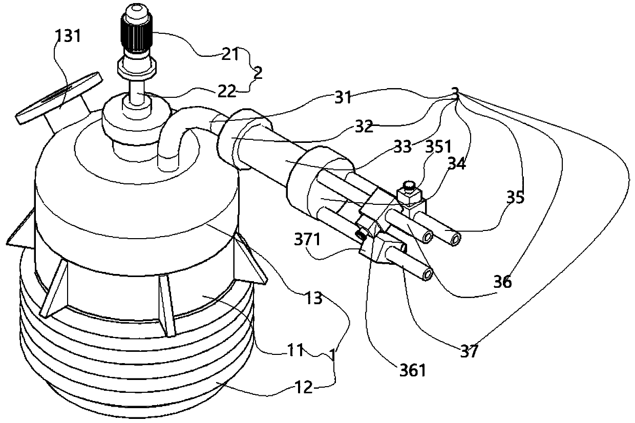
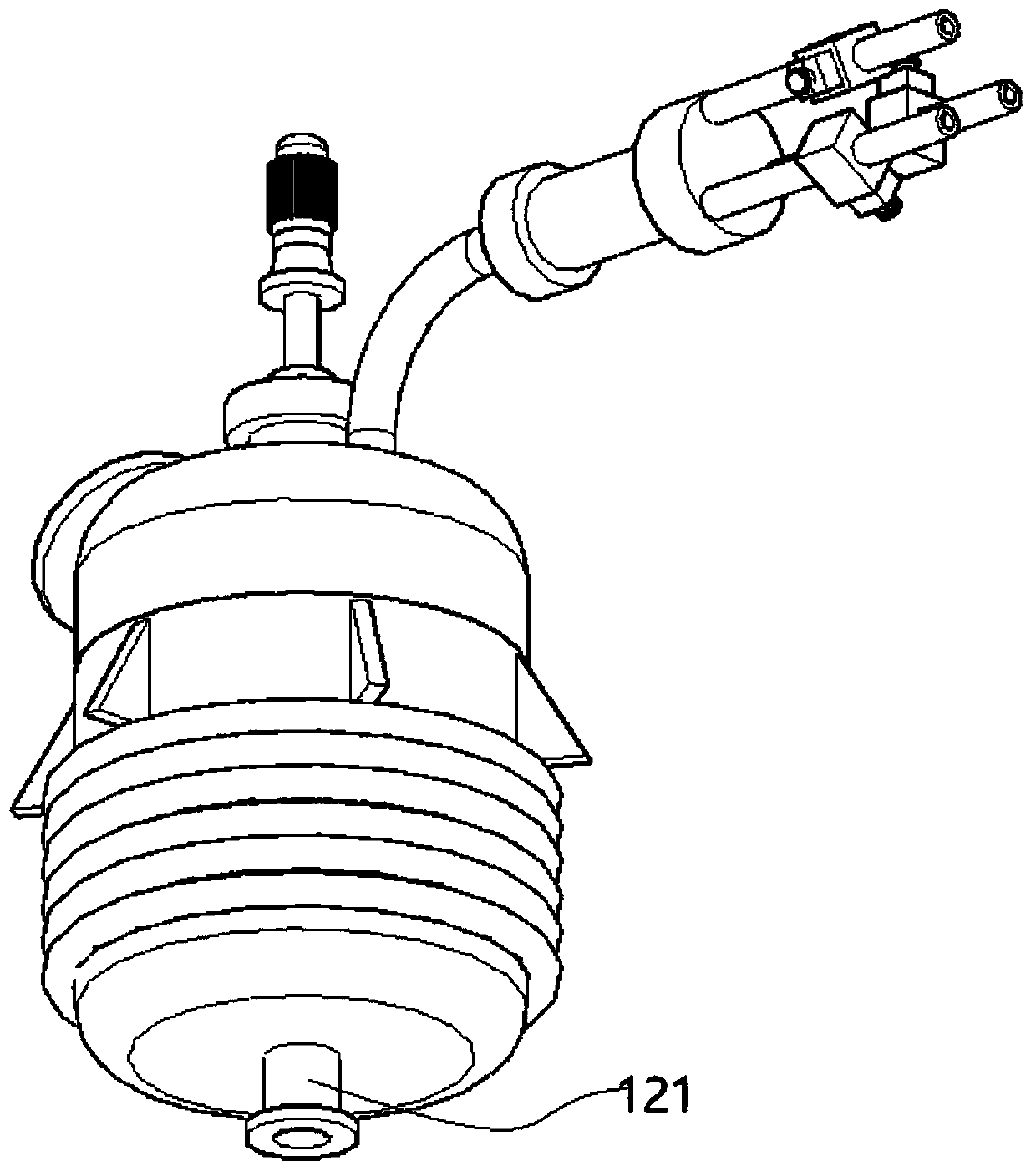
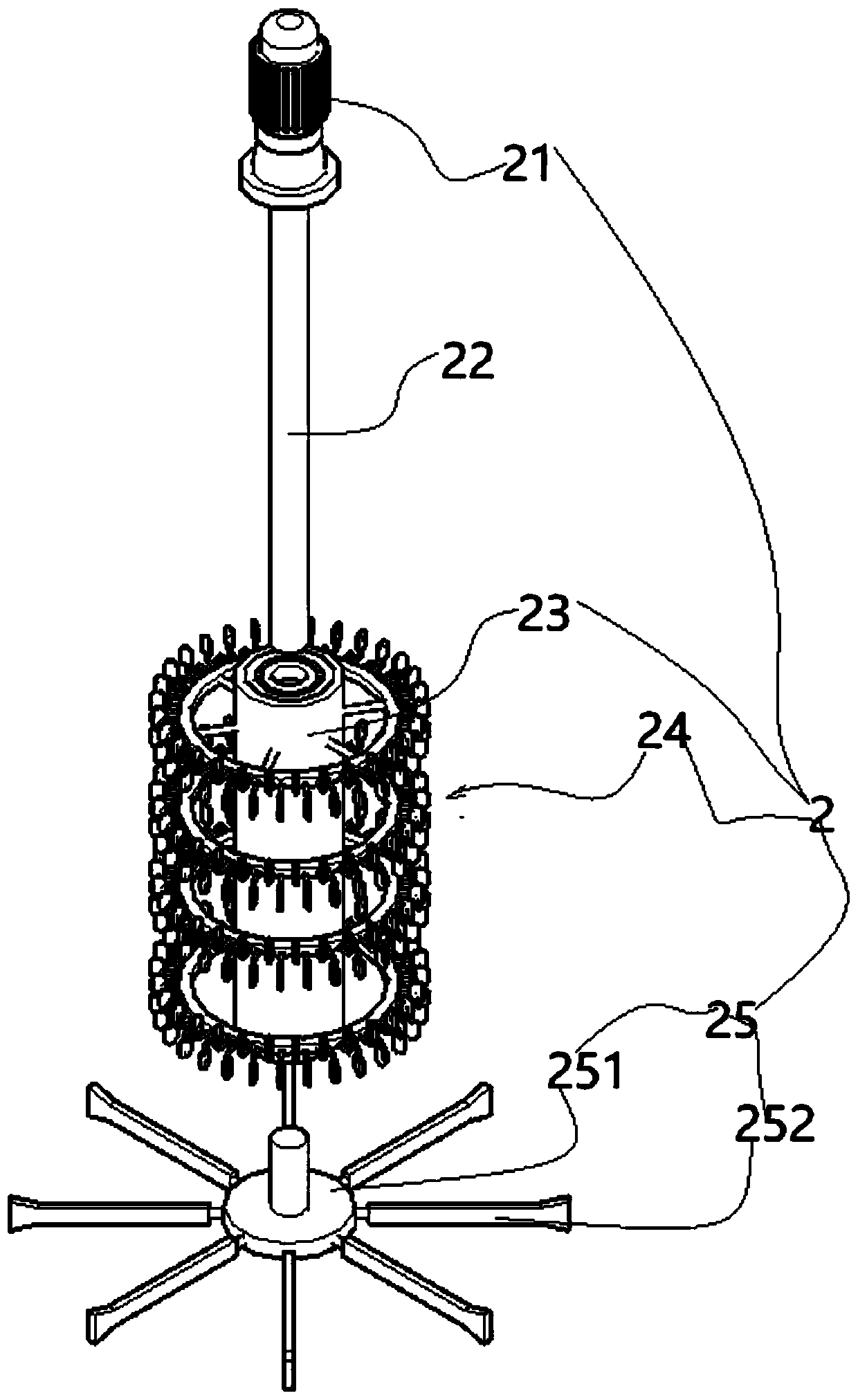
[0047] Such as Figure 1-5 As shown, an automatic and intelligent stirring equipment includes a stirred tank body 1 , and the stirred tank body 1 includes a tank body part 11 and a top cover part 13 assembled on the top of the tank body part 11 . One end of the top cover part 13 is communicated with a feed pipe 131 , and correspondingly, a discharge pipe 121 is communicated with the bottom of the kettle body 11 , and both the feed pipe 131 and the discharge pipe 121 have valves.
[0048] In actual work, in order to realize heating and cooling of the reaction liquid, a spiral protrusion 12 spirally rising is provided at the lower end of the kettle body 11; The wall forms a cavity; the upper end of the spiral protrusion 12 is a liquid outlet, and the liquid outlet is connected with a liquid outlet pipe (the liquid outlet pipe is connected to the heating liquid or cooling liquid inlet device), and the spiral protrusion 12 The lower end is a liquid inlet, and the liquid inlet is ...
Embodiment 2
[0062] Such as Figure 1-8 As shown, this embodiment is based on Embodiment 1, and the other end of the top cover part 13 is communicated with a material liquid pumping component 3 through which the liquid material is pumped. Specifically, the material liquid pumping assembly 3 includes a feed pipe 31 connected to the top cover portion 13; a filter element is communicated with the feed pipe 31, and the material liquid is filtered through the filter element.
[0063] The filter element is used to filter material liquid; the filter element is communicated with a first material pipe 35, the first material pipe 35 is communicated with a first electromagnetic valve 351, and the filter element is communicated with a second material pipe 36. The second material pipe 36 communicates with a second solenoid valve 361 , and the third material pipe 37 communicates with a third solenoid valve 371 . The filter element includes a first liquid pan 32 connected to the feed pipe 31, and a cavi...
Embodiment 3
[0069] Such as Figure 1-8 As shown, in this embodiment, on the basis of Embodiment 2, the automatic intelligent stirring equipment also includes a PLC control platform for controlling the opening and closing of the first electromagnetic valve 351, the second electromagnetic valve 361, and the third electromagnetic valve 371 (in the figure not shown).
[0070] During the stirring process, it is necessary to add different reaction liquids at different times according to the reaction conditions. Therefore, intelligent control is realized through the PLC control platform. Specifically, the PLC control platform includes a PLC control processor, which controls the opening and closing of the first electromagnetic valve 351, the second electromagnetic valve 361, and the third electromagnetic valve 371 through the PLC control processor. , the first electromagnetic valve 351 is controlled by the PLC control processor to open, and after the feeding is completed, the first electromagnet...
PUM
 Abstract
Description
Claims
Application Information
 - R&D
- Intellectual Property
- Life Sciences
- Materials
- Tech Scout
- Unparalleled Data Quality
- Higher Quality Content
- 60% Fewer Hallucinations
Browse by: Latest US Patents, China's latest patents, Technical Efficacy Thesaurus, Application Domain, Technology Topic, Popular Technical Reports.
© 2025 PatSnap. All rights reserved.Legal|Privacy policy|Modern Slavery Act Transparency Statement|Sitemap|About US| Contact US: help@patsnap.com