Discharging mechanism of automatic cutting system

A technology of discharging mechanism and pushing mechanism, which is applied in metal processing and other directions, can solve problems such as prone to wrinkles, difficult to process, and uneven material, so as to achieve the effects of not easy to wrinkle, increase stacking speed, and facilitate subsequent production

Inactive Publication Date: 2020-07-10
宋建华
View PDF7 Cites 2 Cited by
  • Summary
  • Abstract
  • Description
  • Claims
  • Application Information

AI Technical Summary

Problems solved by technology

When the traditional cutting machine cuts the leather, the leather to be processed is sent to the bottom of the cutter under the action of the conveyor, and then cut by the cutter, so that when the material is fed again, the cut part can be placed on the subsequent leather Under the action of the cutting knife, it is ejected from the bottom of the cutter and falls to the collection frame on the ground. However, in the subsequent collection process of the cut materials, the materials fall randomly, and the piled materials are not smooth enough and need to be sorted manually later, and they are randomly collected. Stacking is prone to wrinkles, and it is not easy to post-processing

Method used


Image

  • Discharging mechanism of automatic cutting system
  • Discharging mechanism of automatic cutting system
  • Discharging mechanism of automatic cutting system

Examples


Embodiment Construction

[0029] The present invention will be described in further detail below in conjunction with the accompanying drawings.

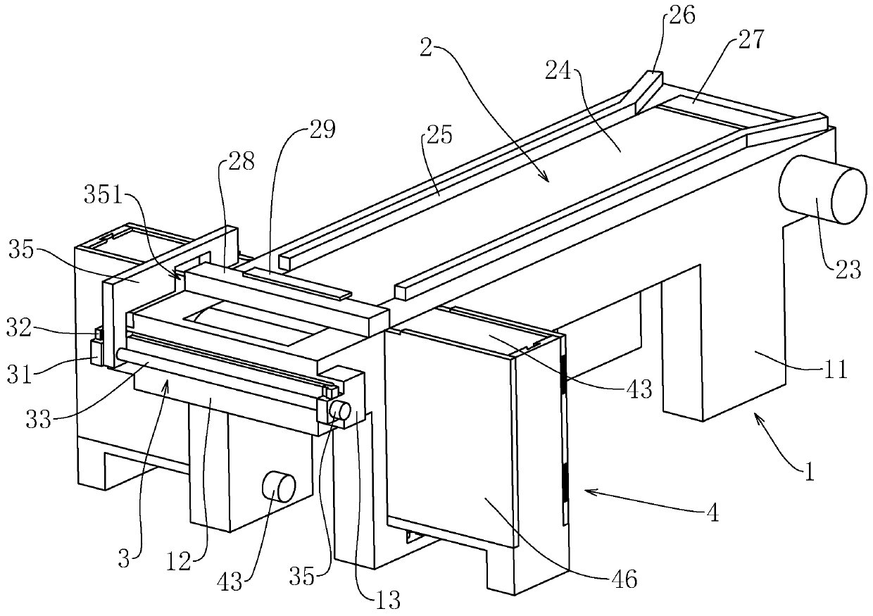
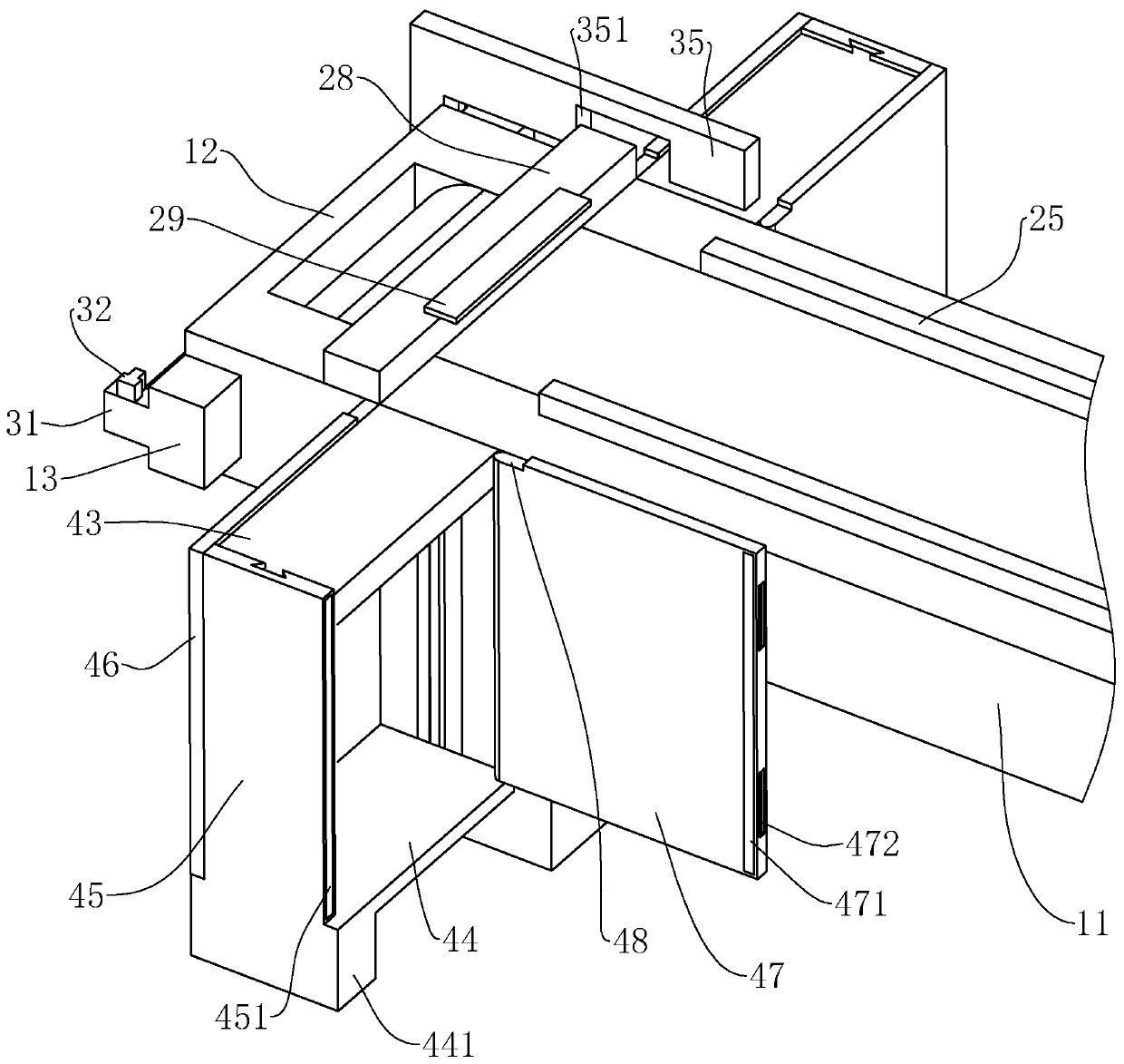
[0030] This embodiment discloses a discharge mechanism of an automatic cutting system, such as figure 1 , figure 2 As shown, it includes a mounting frame 1, a conveying mechanism 2 is connected to the mounting frame 1, a pushing mechanism 3 and two stacking mechanisms 4 are installed on the left end of the mounting frame 1, and the two stacking mechanisms 4 are distributed on the front and rear sides of the mounting frame 1 .

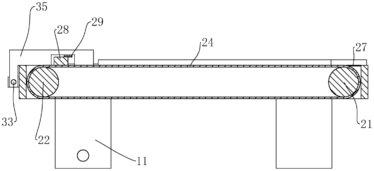
[0031] Such as figure 1 , figure 2 , image 3 As shown, the installation frame 1 includes two support frames 11 and a connecting block 12 connecting the two support frames 11, the conveying mechanism 2 includes a driving roller 21 and a driven roller 22 that are rotatably connected between the two support frames 11, and the driving roller 21 and the driven roller 22 are located at both ends of the support frame 11 respectively, ...


PUM


Abstract

The invention discloses a discharging mechanism of an automatic cutting system. The invention provides the technical scheme points that the discharging mechanism of the automatic cutting system comprises an installation frame, wherein a conveying mechanism is connected onto the installation frame; a pushing mechanism and two stacking mechanisms are arranged at the left end of the installation frame; the installation frame comprises two support frames and two connecting blocks; the conveying mechanism comprises a drive roller and a driven roller rotatably connected between the two support frames; a conveyor belt is tensioned on the drive roller and the driven roller; a drive motor is connected to one end of the drive roller; the pushing mechanism comprises a push rod connected with the connecting block on the left side in a front-and-back sliding way; limiting switches are arranged on the front side and the back side of the push rod; the push rod is connected with the pushing mechanism;a limiting block is fixed to the upper ends of the two support frames; a photoelectric sensor is arranged on the front side of the limiting block; the limiting block is close to the right end of theinstallation frame; a demising groove is formed in the lower end of the push rod; the stacking mechanisms comprise lifting plates connected with the support frames in an up-and-down sliding way; and the lifting plates are connected with a lifting assembly. The discharging mechanism of the automatic cutting system provided by the invention has the functions on flatly staking the cut materials conveniently and providing convenience for post processing.

Description

technical field [0001] The invention relates to the field of cutting, more specifically it relates to a discharge mechanism of an automatic cutting system. Background technique [0002] The cutting machine is used to cut the material and cut the material into a suitable size for processing. When the traditional cutting machine cuts the leather, the leather to be processed is sent to the bottom of the cutter under the action of the conveyor, and then cut by the cutter, so that when the material is fed again, the cut part can be placed on the subsequent leather Under the action of the cutting knife, it is ejected from the bottom of the cutter and falls to the collection frame on the ground. However, in the subsequent collection process of the cut materials, the materials fall randomly, and the piled materials are not smooth enough and need to be sorted manually later, and they are randomly collected. Stacking is prone to wrinkles, and it is not easy to post-processing. Cont...

Claims


Application Information

Patent Timeline
Patent Type & Authority Applications(China)
IPC IPC(8): B26D7/18B26D7/32
CPCB26D7/1818B26D7/32
Inventor 宋建华
Owner 宋建华
Why Eureka
Try Eureka