
a textile bobbin

A yarn bobbin and protection mechanism technology, which is applied in the field of textile yarn bobbin, can solve the problems of side plate and side plate collision, yarn cutting, spinning slippage, etc., so as to prevent yarn from being too loose, excessive load, and yarn The effect of broken lines

Active Publication Date: 2021-11-16
JIANGSU PUMEI TEXTILE CO LTD
View PDF0 Cites 0 Cited by
  • Summary
  • Abstract
  • Description
  • Claims
  • Application Information

AI Technical Summary

Problems solved by technology

[0002] The yarn formed in spinning production needs to be wound into a spindle with a bobbin. During the rotation of the bobbin, the yarn can be rotated, wound and released. The existing textile bobbins are made of aluminum alloy, which is tough and durable. Good heat dissipation, because the yarn is relatively small, when it is wound and released on a smooth aluminum alloy bobbin, there is a phenomenon that the spinning is prone to slipping on the winding shaft, which improves the performance of the yarn when it is wound and released. The probability of intertwined winding, and during rotating use or transportation, collisions between side discs are prone to occur, and burrs are prone to appear on the disc after collision, and the burrs are easy to cut the yarn during rotating use

Method used


Image

  • a textile bobbin
  • a textile bobbin
  • a textile bobbin

Examples


Embodiment 1

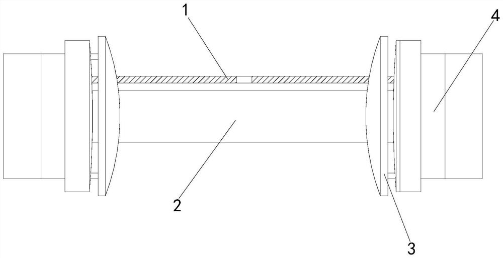
[0025] Such as Figure 1-Figure 5 Shown:

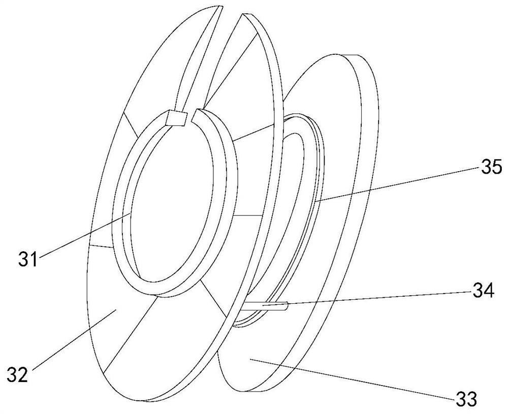
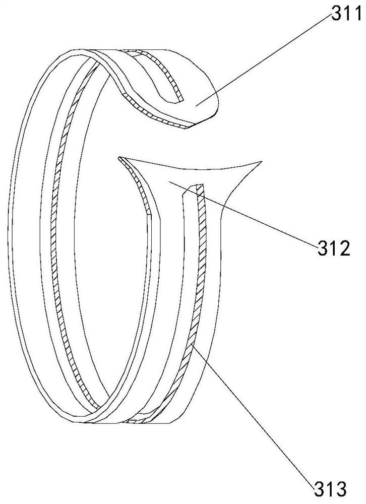
[0026] The present invention is a textile yarn bobbin, the structure of which includes a moving mechanism 1, a winding rod 2, a protection mechanism 3, and a rotating block 4. The winding rod 2 is embedded and installed inside the protection mechanism 3, and the rotating block 4 is fitted On the outside of the protective mechanism 3, the moving mechanism 1 and the winding rod 2 are parallel to each other, and the protective mechanism 3 is installed on both ends of the moving mechanism 1. 33. A connecting rod 34 and a sliding ring 35 are formed. The sliding mechanism 31 is embedded and installed on the left side of the protective disk 32. The sliding ring 35 is welded on the left side of the fixed disk 33. Both ends of the connecting rod 34 are welded on the The right side of the protective disk 32 and the left side of the fixed disk 33, the fixed disk 33 is attached to the inner side of the rotating block 4, the connecting rod 34 is ...

Embodiment 2

[0033] Such as Figure 6-Figure 8 Shown:

[0034]Wherein, the blocking mechanism 14 is provided with a gear rod 141, a rotating block 142, a spring 143, a fixing mechanism 144, and a gap block 145, and the gear rod 141 and the rotating block 142 are engaged with each other, and the gear rod 141 is attached to the spring 143. At the left end, the fixing mechanism 144 is embedded in the right end of the spring 143, the gap block 145 is attached to the right end of the fixing mechanism 144, the gap block 145 is installed at the lower end of the moving block 11, and the rotating block 142 is provided with two symmetrical Distributed on both sides of the spring 143, by turning the rotating block 142 to make the gear lever 141 squeeze the spring 143, it has the effect of adjusting the size of the yarn gap and preventing the yarn from being too loose.

[0035] Wherein, the fixing mechanism 144 is composed of a force-bearing block a1, a rubber rod a2, a compression block a3, a spheri...


PUM


Abstract

The invention discloses a textile yarn bobbin, the structure of which comprises a moving mechanism, a winding rod, a protection mechanism, and a rotating block. Sliding mechanism, protective plate, fixed plate, connecting rod, and sliding ring. Since the yarn rotation direction and angle are fixed, when the yarn moves to the side plate, the sliding mechanism in the protective mechanism slides and slides off the circular block. , the sliding ring prevents the sliding force of the yarn from falling inside the protection mechanism, prevents the yarn from being cut when it rotates, prevents the hydraulic rod from being moved up during the upward movement, and avoids excessive load when moving upward, and the yarn from the circle The shaped hole enters the spherical block, and the rotating block makes the gear lever squeeze the spring, which has the effect of adjusting the size of the yarn gap, preventing the yarn from being too loose. , to avoid yarn breakage.

Description

technical field [0001] The invention relates to the textile field, in particular to a textile yarn bobbin. Background technique [0002] The yarn formed in the spinning production needs to be wound into a spindle with a bobbin. During the rotation of the bobbin, the yarn can be rotated, wound and released. The existing textile bobbin is made of aluminum alloy, which is tough and durable. Good heat dissipation, because the yarn is relatively small, when it is wound and released on a smooth aluminum alloy bobbin, there is a phenomenon that the spinning is prone to slipping on the winding shaft, which improves the performance of the yarn when it is wound and released. The probability of intertwined winding, and during rotating use or transportation, collisions between side discs are prone to occur, and after collisions, the variable discs are prone to burrs, and the burrs are easy to cut the yarn during rotating use. Contents of the invention [0003] The present invention i...

Claims


Application Information

Patent Timeline
Patent Type & Authority Patents(China)
IPC IPC(8): B65H75/14B65H75/18
CPCB65H75/14B65H75/18B65H2701/31
Inventor 黄建中
Owner JIANGSU PUMEI TEXTILE CO LTD
Learn More