Method and device for recovering oil and gas

A technology for oil, gas and gasoline, which is applied in the recovery of liquid hydrocarbon mixture, gas fuel, petroleum industry, etc. It can solve the problems affecting the quality of ethylbenzene and styrene products, the heat load of the reboiler at the bottom of the tower, the increase of investment and energy consumption, etc. , to achieve the effects of easing operating conditions, reducing energy consumption, and cooling capacity consumption

Active Publication Date: 2022-05-24
SINOPEC ENG +1
View PDF15 Cites 0 Cited by
  • Summary
  • Abstract
  • Description
  • Claims
  • Application Information

AI Technical Summary

Problems solved by technology

[0005] (2) The absorption and stabilization system uses stable gasoline as an absorbent to recover liquefied gas components. Due to the high yield of liquefied gas components in the catalytic cracking process, gasoline is Gasoline absorbing tower, ethane deabsorbing tower and stabilizing tower are circulated, and the circulation volume is large, the temperature at the bottom of ethane desorbing tower and stabilizing tower is high, the heat load of reboiler at the bottom of the tower is relatively large, and the energy consumption is low high
[0006] (3) The entire technological process is relatively long, which increases investment and energy consumption accordingly
[0007] (4) When the recovered C2 product is sent to the separation unit of the ethylene plant, some of the heavy components such as propylene contained in the C2 product can be recovered through the ethylene separation unit; but when the recovered C2 product is sent to the downstream production of ethylbenzene , the propylene component contained in it will bring many adverse effects to the production of ethylbenzene, which will not only greatly increase the consumption of benzene, but also directly affect the quality of ethylbenzene and styrene products
Due to the low boiling point of the carbon 2 component, the separation of the carbon 2 and carbon 3 components usually requires a temperature of -5 to -20°C. For this reason, dehydration and CO removal are required 2 processing, and requires a lower temperature grade of refrigerant, the investment and energy consumption are large
[0008] (5) The existing process desulfurizes and sweetens the dry gas and liquefied gas after absorption and stabilization, H 2 S and mercaptans circulate in the entire absorption stabilization system, which may cause related corrosion problems, and there is H in the entire absorption stabilization system. 2 Possible security issues caused by S leakage

Method used


Image

  • Method and device for recovering oil and gas
  • Method and device for recovering oil and gas
  • Method and device for recovering oil and gas

Examples


Embodiment 1

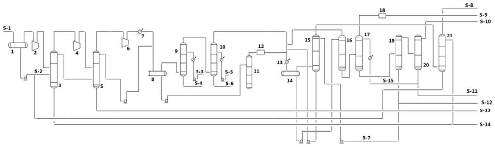
[0090] Devices for oil and gas recovery include:

[0091] Oil and gas feed line, gas-liquid separation tank I1, compressor I2, light and heavy gasoline separation tower 3, compressor II4, light hydrocarbon-light gasoline separation tower 5, compressor III6, cooler I7, gas-liquid separation tank II8 , rich gas desulfurization tower 9, rich gas alkali washing tower 10, liquid hydrocarbon desulfurization tower 11, liquid hydrocarbon desulfurization reactor 12, cooler II 13, feed tank 14, absorption tower 15, demethanizer 16, deethanizer 17. Depropanizer 19, propylene rectification / 20 and absorbent recovery tower 21;

[0092] Wherein, the oil and gas feed line is connected with the inlet of the gas-liquid separation tank 11, the top of the gas-liquid separation tank 11 is connected with the compressor 12, the light and heavy gasoline separation tower 3 in turn, and the bottom of the tank is connected with the light and heavy gasoline separation tower 5;

[0093] Light and heavy g...

Embodiment 2

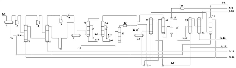
[0128] using as figure 2 The shown technological process recovers oil and gas, and the difference from Example 1 is: in this example, the part of the mixed C4 component S-15 extracted from the bottom of the depropanizer 19 is used in the deethanizer 17 as the Absorbent to separate C2 components.

[0129] Wherein, the mixed C 4 absorbent S-12 drawn from the bottom of the depropanizer 19 and sent back to the deethanizer 17 is 5000kg / h, and the recovered product compositions, flow rates and properties are shown in Tables 5 and 6 :

[0130] table 5

[0131]

[0132]

[0133] Table 6

[0134]

Embodiment 3

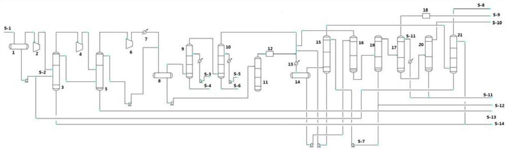
[0136] using as image 3 The shown technological process recovers oil and gas, and the difference from Example 1 is: in this example, the sequence of demethanization, depropanization, and deethanization is successively used to separate light hydrocarbons, wherein, the top of the deethanizer 17 is separated. Part of the propane taken from the bottom of the propylene rectifying tower 20 is used as the absorbent S-11 to separate the C2 component.

[0137] Wherein, the propane absorbent S-11 that is sent back to the deethanizer 17 extracted from the bottom of the propylene rectifying tower 20 is 6500kg / h, and each product composition, flow rate and property recovered are shown in Table 7, Table 8:

[0138] Table 7

[0139]

[0140]

[0141] Table 8

[0142]

[0143]

[0144] As can be seen from the data in the above table, the process of the present invention is simple, the operating conditions are moderate, the consumption of cooling energy is low, and the separatio...


PUM

PropertyMeasurementUnit
dry pointaaaaaaaaaa

Abstract

The invention belongs to the field of chemical industry, and specifically discloses a method and device for recovering oil and gas. The method has simple process flow, moderate operating conditions, less cooling capacity consumption, and can realize the recovery of light and heavy gasoline, carbon two, carbon three and Efficient separation and recovery of carbon four components, especially the efficient separation and recovery of carbon two, carbon three and carbon four components, and the recovered carbon two products basically do not contain propylene, which can be sent downstream to directly produce ethylbenzene / styrene; and the present invention adopts gas phase and liquid phase to desulfurize and desulfurize respectively, the gas phase desulfurizes and desulfurizes under high pressure, the equipment volume is small, the investment is low, and the desulfurization effect is good; at the same time, the heavy hydrocarbon content in the gas phase The reduction can prevent heavy hydrocarbons from condensing into the amine liquid, and can effectively avoid the foam entrainment of the desulfurization device caused by the foaming of the amine liquid, ensuring the smooth operation of the device.

Description

technical field [0001] The invention belongs to the field of oil refining and chemical industry, more particularly, relates to a method and device for recovering oil and gas, and more particularly relates to a device for recovering oil and gas in processes with high gas yields such as catalytic cracking, catalytic cracking and delayed coking, and the like. method. Background technique [0002] Light hydrocarbons refer to the components obtained from petrochemical processes such as methane, ethane, ethylene, propane, propylene, and C4. The separation process of light hydrocarbons has always been the focus of petrochemical processes. Among them, the separation process between carbon two, carbon three and carbon four is relatively mature, and the method of rectification is usually used. Due to its low boiling point, methane needs to be cooled to -100°C and lower if the rectification method is used to separate methane and carbon dioxide, that is, cryogenic separation, which is ...

Claims


Application Information

Patent Timeline
Patent Type & Authority Patents(China)
IPC IPC(8): C10G5/00C10G53/12C10L3/00
CPCC10G5/00C10G53/12C10L3/00
Inventor 黄孟旗余龙红吴雷丁昱文吴迪
Owner SINOPEC ENG
Why Eureka
Try Eureka