Unlock instant, AI-driven research and patent intelligence for your innovation.

Device and method for quickly detecting hole site deviation

A hole location and fast technology, applied in the direction of measuring devices, mechanical devices, mechanical measuring devices, etc., can solve the problems of not being able to know the correction area, the distance between the drilling mold hole and the hole making hole, and the large difference in hole diameter, etc., to achieve The effect of convenient and efficient detection, guaranteed accuracy and improved accuracy

Active Publication Date: 2020-07-10
CHENGDU AIRCRAFT INDUSTRY GROUP
View PDF9 Cites 0 Cited by
  • Summary
  • Abstract
  • Description
  • Claims
  • Application Information

AI Technical Summary

Problems solved by technology

[0003] Although it is convenient to manually observe whether the drilling holes are included in the drilling holes through the drilling holes, the distance between the drilling holes and the drilling holes is far away, and the difference in diameter between the two holes is too large, which makes the detection results extremely difficult. Unreliable, and the test results cannot be quantified
However, the existing rapid detection tool can only determine whether the deviation hole position can be corrected, but the specific correction area cannot be known after the detection tool is removed, making subsequent correction operations inconvenient
In addition, the laser tracker is used to detect the deviation of the hole position by measuring the spatial coordinates of the center of each hole-making hole and the center of the drilling mold hole, and judging whether there is a deviation in the hole-making hole according to these two coordinates. This detection method has a high detection accuracy. , but when detecting a large number of hole-making deviations, there are problems such as high equipment cost, inconvenient detection and low efficiency
[0004] Therefore, in view of the defects in the existing hole-making deviation detection device and method that the detection accuracy of manual visual inspection is insufficient, the inspection of ordinary hole-making tools cannot know the hole-making correction area, and the laser detection cost is high and the efficiency is low, the present invention discloses A device and method for rapid detection of hole position deviation

Method used


Image

  • Device and method for quickly detecting hole site deviation
  • Device and method for quickly detecting hole site deviation
  • Device and method for quickly detecting hole site deviation

Examples


Embodiment 1

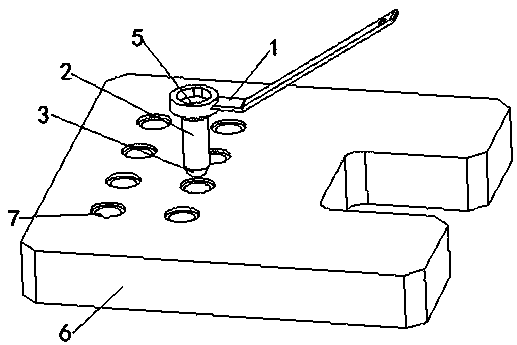
[0036]A device and method for rapid detection of hole position deviation in this embodiment, such as Figure 1-Figure 3 As shown, it includes a handle 1, one end of the handle 1 is equipped with a detection pin 2, and the end of the detection pin 2 away from the handle 1 is coaxially provided with a positioning cone 3, and the inside of the detection pin 2 is provided with a penetration detection pin along the axis. The observation hole 5 of the pin 2 and the positioning cone 3 is provided with a calibration pen 4 on the end surface of the positioning cone 3 away from the detection pin 2 .

[0037] The detection pin 2 is a hollow columnar structure, and the outer diameter of the detection pin 2 is equal to the diameter of the drill hole 7, and the outer diameter of the detection pin 2 is usually set to 10mm. During the detection process, the detection pin 2 is inserted into the drilling mold hole 7 on the drilling mold 6. When the end face of the positioning cone 3 at the bott...

Embodiment 2

[0043] This embodiment is further optimized on the basis of embodiment 1, such as image 3 and Figure 4 As shown, the end surface of the positioning cone 3 away from the detection pin 2 is provided with a mounting groove 01, and the interior of the mounting groove 01 is provided with a tightening spring 02 and a calibration pen 4, and one end of the calibration pen 4 passes through the top The tight spring 02 is connected to the groove bottom end surface of the installation groove 01 , and the calibration end of the calibration pen 4 extends to the outside of the installation groove 01 .

[0044] The edge of the calibration end of the calibration pen 4 is provided with a limit ring, and the inner edge of the opening of the installation groove 01 is provided with a limit flange corresponding to the limit ring on the calibration end of the calibration pen 4 .

[0045] Under the action of the tightening spring 02, the nib of the calibration pen 4 is located outside the opening ...

Embodiment 3

[0050] This embodiment is further optimized on the basis of above-mentioned embodiment 1 or 2, such as Figure 5 As shown, the end of the detection pin 2 close to the handle 1 is coaxially provided with a clamping part, and the end of the handle 1 close to the detection pin 2 is provided with a clamping seat corresponding to the clamping part on the detection pin 2. The part and the clamping seat are engaged with each other.

[0051] A mounting hole is coaxially provided on the clamping seat corresponding to the clamping portion, a clamping groove is provided on an end surface of the mounting hole, and a card is provided at one end of the clamping portion.

[0052] One end of the detection pin 2 is provided with a cylindrical locking portion, and two cards are evenly arranged on the edge of the top end surface of the locking portion along the circumferential direction, that is, the positions between the two cards are arranged at an interval of 180°. At the same time, one end ...


PUM


Abstract

The invention discloses a device for quickly detecting a hole site deviation. The device comprises a detection pin arranged at one end of a handle. A positioning cone is coaxially arranged at one endof the detection pin, an observation hole penetrating through the detection pin and the positioning cone is arranged in the detection pin along an axis, and a calibration pen is arranged on an end surface of one end of the positioning cone. The invention further discloses a method for quickly detecting the hole site deviation. A detection pin is inserted into a drill jig hole, the observation holearranged in the detection pin is used for directly observing a hole forming hole site so as to determine whether the hole forming hole site can be subjected to hole site deviation correction or not,meanwhile, a series of detection pins with the observation holes with the hole diameters which are sequentially increased are arranged to detect the hole forming hole site, and therefore quantification of the hole forming hole site is achieved. Meanwhile, the subsequent hole site deviation correction area is subjected to remembering calibration through the calibration pen; the device and the method have beneficial effects of simple operation, high detection efficiency, high detection precision, and capabilities of quantifying the hole site deviation and calibrating the hole site deviation correction area.

Description

technical field [0001] The invention belongs to the technical field of hole position deviation detection, and in particular relates to a device and method for fast detection of hole position deviation. Background technique [0002] Hole-making processing operation is generally a key step in the assembly process of aviation products. A large number of connection structures in aviation products need to be connected by hole-making, riveting and other processes, especially for holes with multiple holes on the surface of the connection structure. In terms of bit processing, it should be ensured that the hole positions of the interconnected parts are coordinated and consistent. Therefore, it is a key link in the hole making process to effectively and reliably detect the correctness of the machining hole position through the corresponding detection technology, and this operation is of great significance to ensure the assembly quality of the aircraft. In the process of hole making,...

Claims


Application Information

Patent Timeline
Patent Type & Authority Applications(China)
IPC IPC(8): G01B5/00
CPCG01B5/0002
Inventor 朱国仁熊钦林段作衡卢大伟郭喜锋孔德帅黎晶
Owner CHENGDU AIRCRAFT INDUSTRY GROUP