State switching system and method for object

A state switching and state technology, applied in the computer field, can solve problems such as state switching problems

Active Publication Date: 2020-07-10
SHANGHAI MIHOYO TIANMING TECH CO LTD
View PDF4 Cites 1 Cited by
  • Summary
  • Abstract
  • Description
  • Claims
  • Application Information

AI Technical Summary

Problems solved by technology

[0003] It can be seen that in the prior art, when the logic state is switched, the logic state and the animation state affect each other. If the variable of the record id is changed when the animation transitions, or some situations occur in the animation state machine (for example, it is reset or the trigger priority is higher transitions that override the original transition) can cause problems with state transitions

Method used


Image

  • State switching system and method for object
  • State switching system and method for object
  • State switching system and method for object

Examples


Embodiment 1

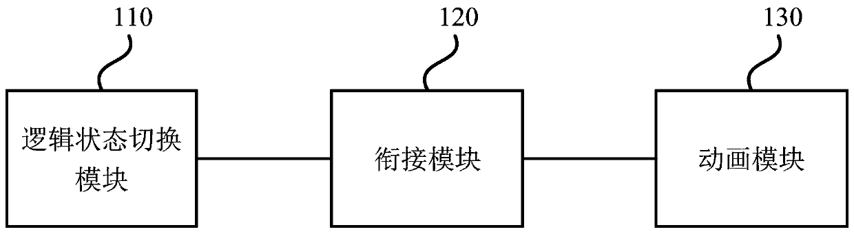
[0041] Figure 1a It is a schematic structural diagram of a logic state switching system provided by Embodiment 1 of the present invention. This embodiment is applicable to the situation of switching the state of the object, especially applicable to the situation of switching the state of the game object. Such as Figure 1a As shown, the system includes a logic state module 110, a connection module 120 and an animation module 130, wherein:

[0042] The logic state switching module 110 is configured to obtain a logic state to be switched, and perform logic state switching according to the logic state to be switched;

[0043] The connection module 120 encapsulates the execution interface in the animation module, and is used to forward the events of the logic state module and / or the animation module;

[0044] The animation module 130 is used for animation switching.

[0045] In this embodiment, by using a reusable middle layer SoC structure (Separation of Concerns Architecture)...

Embodiment 2

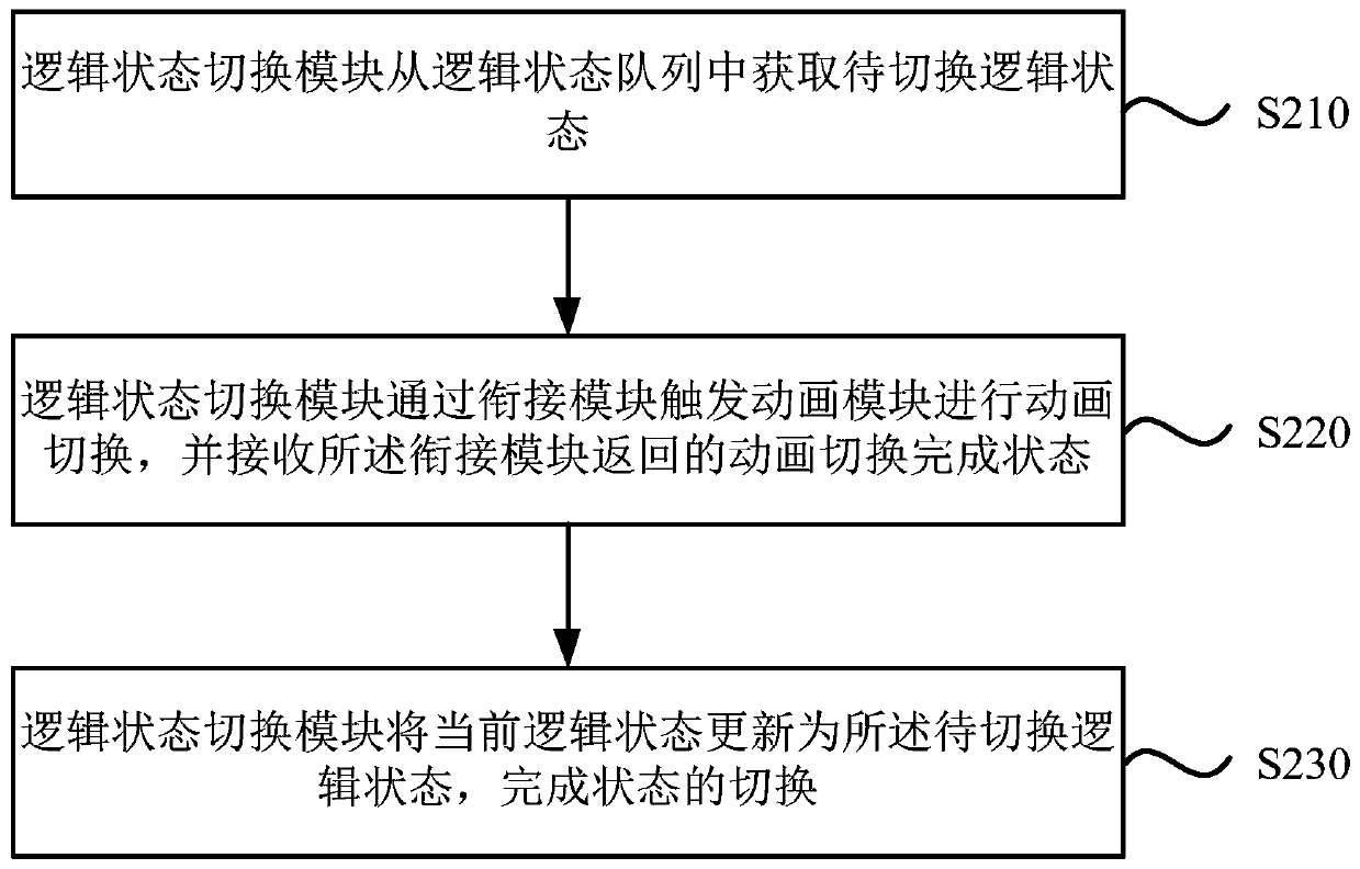
[0071] figure 2 It is a flowchart of a state switching method provided by Embodiment 2 of the present invention. This embodiment is applicable to the situation of switching the state of the object, especially applicable to the situation of switching the state of the game object. The method can be executed by a logic state switching device, and the logic state switching device can be implemented in software and / or hardware, for example, the logic state switching device can be configured in a logic state switching device. As shown in Figure 1, the method includes:

[0072] S110. The logic state switching module obtains the logic state to be switched from the logic state queue.

[0073] In this embodiment, a queue is used instead of a single state machine in the prior art, which has better scalability compared with the prior art. The logical state switching module obtains the next logical object state from the state pool, puts the logical object state into the logical state q...


PUM


Abstract

The embodiment of the invention discloses a state switching system and method for an object, and the system comprises a logic state module, a connection module, and an animation module, and the logicstate switching module is used for obtaining a to-be-switched logic state, and carrying out the switching of the logic state according to the to-be-switched logic state; the connection module is packaged with an execution interface in the animation module and is used for forwarding an event of the logic state module and / or the animation module; and the animation module is used for animation switching. According to the state switching system provided by the embodiment of the invention, the events of the logic state module and / or the animation module are forwarded by using the connection module,so decoupling of the logic state switching module and the animation module is realized, and the code development complexity and the execution logic of the logic state switching layer are simplified.

Description

technical field [0001] The embodiments of the present invention relate to the field of computer technology, and in particular to a state switching system and method for objects. Background technique [0002] Unity currently plays animations mainly through the animation state machine. A game object usually needs a logic manager to manage the logic state (movement, attack, etc.), and an animation state machine is needed to play the current animation corresponding to the logic state, such as running and skill animation. The logic manager is usually a loop. Each frame updates the logic state first, then updates the animation state, and continues the above content in the next frame. The process when switching from one logical state to the next is as follows: 1. Start switching states, record the Id of the next state, set the animation id of the animation state machine, and the animation state machine starts to do animation fusion transition. 2. In each frame of the loop of the l...

Claims


Application Information

Patent Timeline
Patent Type & Authority Applications(China)
IPC IPC(8): G06F8/20G06T13/00
CPCG06F8/24G06T13/00
Inventor 程思鹏
Owner SHANGHAI MIHOYO TIANMING TECH CO LTD
Why Eureka
Try Eureka