Electric locomotive motor system

A technology for electric locomotives and motor bodies, applied in the field of electric motors, can solve the problems of manual adjustment of output power and poor passability, and achieve good energy utilization efficiency, output torque enhancement, and high energy utilization efficiency

Inactive Publication Date: 2020-07-10
李聪
View PDF0 Cites 0 Cited by
  • Summary
  • Abstract
  • Description
  • Claims
  • Application Information

AI Technical Summary

Problems solved by technology

When driving on bumpy roads, if the output power cannot be adjusted flexibly, the electric locomotive is likely to have poor passability due to insufficient power.
Especially for toy electric vehicles, because they are far away from the operator after starting, it is basically impossible to manually adjust their output power in real time according to the road conditions during driving, resulting in poor passability

Method used


Image

  • Electric locomotive motor system
  • Electric locomotive motor system
  • Electric locomotive motor system

Examples


Embodiment 1

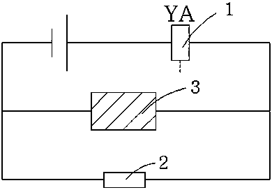
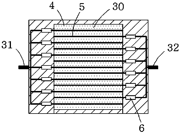
[0014] Such as Figure 1 to Figure 3 In the first embodiment shown, the electric locomotive motor system includes a motor body, which has an excitation device 1 that provides a working magnetic field, and the excitation device 1 is electrically connected to the power supply through a fixed value resistor 2; and in the fixed value A dynamic resistor 3 is connected in parallel on the value resistance 2; the dynamic resistor 3 includes a closed cavity 30, and mercury 4 is sealed in the cavity 30, and mercury 4 is equidistantly distributed at intervals of 1 mm to 2 mm above the liquid surface Conductive metal rods 5 parallel to each other and extending longitudinally along the entire inner cavity 30, and one of the two adjacent conductive metal rods 5 is electrically connected to the dynamic resistor after a protective resistor 6 is connected in series The first electrode 31 of the dynamic resistor 3 is electrically connected to the second electrode 32 of the dynamic resistor 3 af...

Embodiment 2

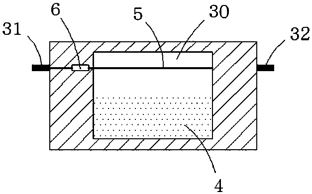
[0018] Such as Figure 4 The difference between the shown embodiment two and the first embodiment is that the inner bottom surface of the inner cavity 30 is made into a wave surface that undulates along the running direction of the electric locomotive; In the process of acceleration and deceleration with higher requirements, even under the flat terrain, the mercury 4 can form large undulations and contaminate the conductive metal rod 5 under the oblique thrust of the wave surface, so that Temporarily increase the output power of the motor.


PUM


Abstract

The invention provides an electric locomotive motor system, which comprises a motor body, and is characterized in that the motor body is internally provided with an excitation device for providing a working magnetic field, and the excitation device is electrically connected to a power supply through a constant value resistor; a dynamic resistor is connected in parallel to the constant-value resistor; the dynamic resistor comprises a closed inner cavity; mercury is sealed in the inner cavity; conductive metal rods which are parallel to each other and extend along the longitudinal direction of the whole inner cavity are equidistantly distributed above the mercury liquid level at intervals of 1-2mm; and one of the two adjacent conductive metal rods is electrically connected to a first electrode of the dynamic resistor after being connected with a protective resistor in series, and the other conductive metal rod is electrically connected to a second electrode of the dynamic resistor afterbeing connected with the protective resistor in series. The motor system can automatically adjust the output power of a motor according to the real-time road surface condition of the electric locomotive, so that the electric locomotive obtains better road surface trafficability.

Description

technical field [0001] The invention relates to the field of electric motors, in particular, to a vehicle electric motor. Background technique [0002] The electric motor installed on the small electric locomotive at present, its output power depends on the adjustment of the control switch, which is not obviously insufficient when driving on a flat road. When driving on bumpy roads, if the output power cannot be adjusted flexibly, the electric locomotive is likely to have poor passability due to insufficient power. Especially for toy electric vehicles, because they are far away from the operator after starting, it is basically impossible to manually adjust their output power in real time according to the road conditions during driving, resulting in poor passability. Contents of the invention [0003] In view of the above problems, the object of the present invention is to provide an electric locomotive motor system, which can automatically adjust the output power of the m...

Claims


Application Information

Patent Timeline
Patent Type & Authority Applications(China)
IPC IPC(8): H02K11/00
CPCH02K11/0094
Inventor 李聪
Owner 李聪
Why Eureka
Try Eureka