Unlock instant, AI-driven research and patent intelligence for your innovation.

Synchronous rectification control method and synchronous rectification control circuit for self-adaptive detection time

A technology of self-adaptive detection and synchronous rectification, which is applied in the direction of electrical components, output power conversion devices, AC power input conversion to DC power output, etc., to achieve the effects of improving conversion efficiency, easy integration, and stable and reliable control

Active Publication Date: 2020-07-10
SOUTHCHIP SEMICON TECH SHANGHAI CO LTD
View PDF8 Cites 8 Cited by
  • Summary
  • Abstract
  • Description
  • Claims
  • Application Information

AI Technical Summary

Problems solved by technology

[0006]Aiming at the above-mentioned synchronous rectification control by detecting the slope of the drain-source voltage VDS falling edge of the synchronous rectification switch, the problem of indistinguishable freewheeling and oscillation of the secondary side leading to false turn-on problems, The present invention proposes a control method for a synchronous rectification circuit with self-adaptive detection time, which performs synchronous rectification control by detecting the peak voltage of the drain-source voltage of the synchronous rectification switching tube, sets the detection time for voltage platform identification, and can accurately perform switching power supply The opening judgment of the secondary synchronous rectification does not have the false opening problem of the traditional slope detection method, and can be used in scenarios where the slope detection method cannot be applied; in addition, the present invention also proposes a detection time adaptive voltage platform identification method, which can further improve the lightness of the system. load efficiency and control accuracy

Method used


Image

  • Synchronous rectification control method and synchronous rectification control circuit for self-adaptive detection time
  • Synchronous rectification control method and synchronous rectification control circuit for self-adaptive detection time
  • Synchronous rectification control method and synchronous rectification control circuit for self-adaptive detection time

Examples


Embodiment Construction

[0056] The technical solution of the present invention will be described in detail below in conjunction with the accompanying drawings and specific embodiments.

[0057] The synchronous rectification control method and control circuit proposed by the present invention are suitable for switching power supplies, including flyback, forward, LLC, etc., and the following uses the application of the present invention to flyback switching power supplies as an example to illustrate, according to the present invention The idea can be used for other switching power supply types as well.

[0058] Such as figure 2 and Figure 8 Shown is a schematic diagram of applying the present invention to the low-side drive and high-side drive of the switching power supply. The primary side of the switching power supply includes the primary winding and the switching tube Q1, and the secondary side includes the secondary winding, the capacitor C1 and the synchronous rectification switching tube QSR. ...


PUM


Abstract

The invention discloses a synchronous rectification control method and a synchronous rectification control circuit for self-adaptive detection time, and belongs to the technical field of switching power supplies. According to the invention, the drain-source voltage of a synchronous rectification switching tube is detected in real time; when the drain-source voltage of the synchronous rectificationswitching tube is detected to be at the peak, a judgment voltage is set according to the peak voltage monitored in real time, and the drain-source voltage of the synchronous rectification switching tube within a self-adaptive set detection time after the peak arrives is compared with the judgment voltage; and when the drain-source voltage of the synchronous rectification switching tube is greaterthan the judgment voltage and less than a threshold voltage, an effective gate driving signal of the synchronous rectification switching tube is generated to turn on the synchronous rectification switching tube. According to the invention, the waveform flied back to the secondary side by primary side conduction and the waveform of self-oscillation of the secondary side can be accurately distinguished, accurate turn-on judgment of secondary synchronous rectification is realized, and the problem of false turn-on caused by a traditional slope detection mode is solved. The detection time is set in a self-adaptive manner, so that the light load efficiency and the control precision of the system are further improved.

Description

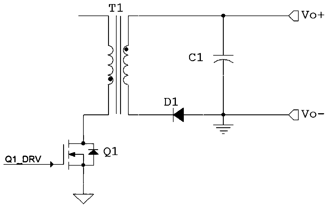
technical field [0001] The invention belongs to the technical field of switching power supplies, and relates to an adaptive detection time synchronous rectification control method and a control circuit for realizing the self-adaptive detection time synchronous rectification control method. Background technique [0002] Such as figure 1 Shown is a partial structure of an AC-DC switching power supply system. The primary winding of the transformer is connected to the switch tube Q1, and the secondary winding is connected to the diode D1. The secondary side of the traditional flyback converter has only one diode D1. However, due to the increasing energy efficiency requirements High, the forward voltage drop of the diode is generally above 0.7V, so the power consumption of the traditional solution is particularly large, and it is becoming more and more difficult to meet the energy consumption requirements. [0003] Therefore, it is proposed to replace the diode D1 in the traditi...

Claims


Application Information

Patent Timeline
IPC IPC(8): H02M7/217H02M1/08
CPCH02M7/217H02M1/08Y02B70/10
Inventor 卞坚坚高建龙
Owner SOUTHCHIP SEMICON TECH SHANGHAI CO LTD