Installation and fixing device of a temperature-controlled optical transmitter

A fixed device, optical transmitter technology, used in electromagnetic transmitters, supporting machines, mechanical equipment, etc., can solve the problems of large space occupied, dragging on the table, falling to the ground, etc., to reduce the space occupied, Avoid the effect of cleaning work

Active Publication Date: 2021-06-08
南瑜璇
View PDF10 Cites 0 Cited by
  • Summary
  • Abstract
  • Description
  • Claims
  • Application Information

AI Technical Summary

Problems solved by technology

[0004] The invention provides an installation and fixing device for a temperature-controlled optical transmitter, which effectively solves the problem that most people directly place the temperature-controlled optical transmitter on the table when using the temperature-controlled optical transmitter at present, and the temperature-controlled optical transmitter The optical cable connected to the optical transmitter will be dragged on the table, which takes up a lot of space, and when the table is shaken, the temperature-controlled optical transmitter is easy to slide on the table and fall to the ground, causing damage. The temperature-controlled optical transmitter is raised, which is a more troublesome problem

Method used


Image

  • Installation and fixing device of a temperature-controlled optical transmitter
  • Installation and fixing device of a temperature-controlled optical transmitter
  • Installation and fixing device of a temperature-controlled optical transmitter

Examples


Embodiment

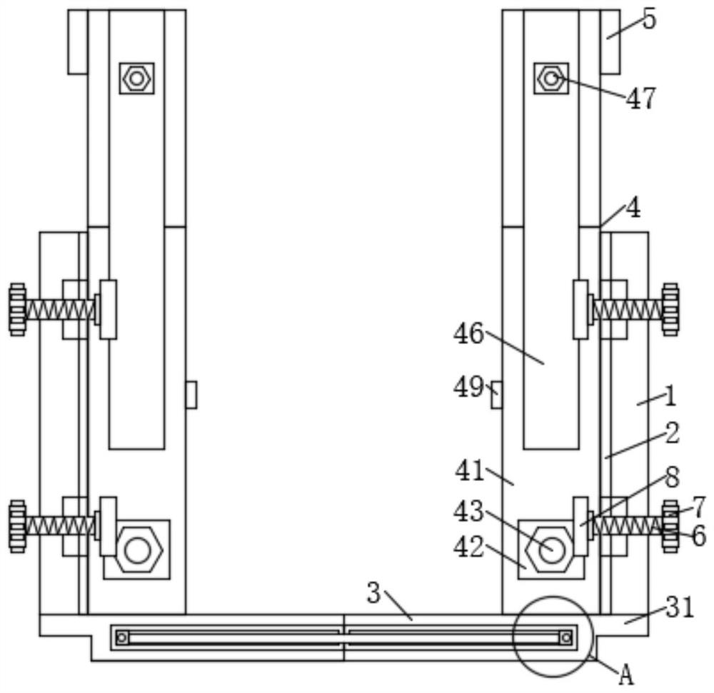
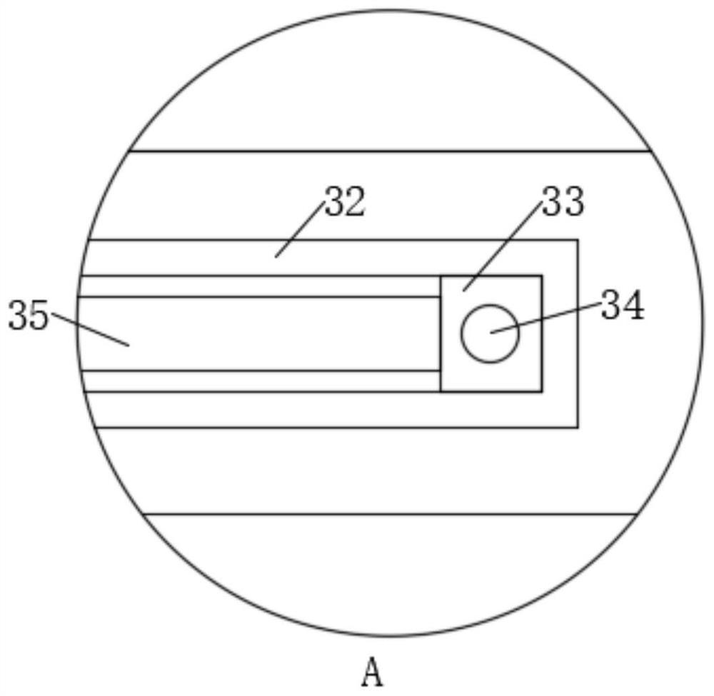
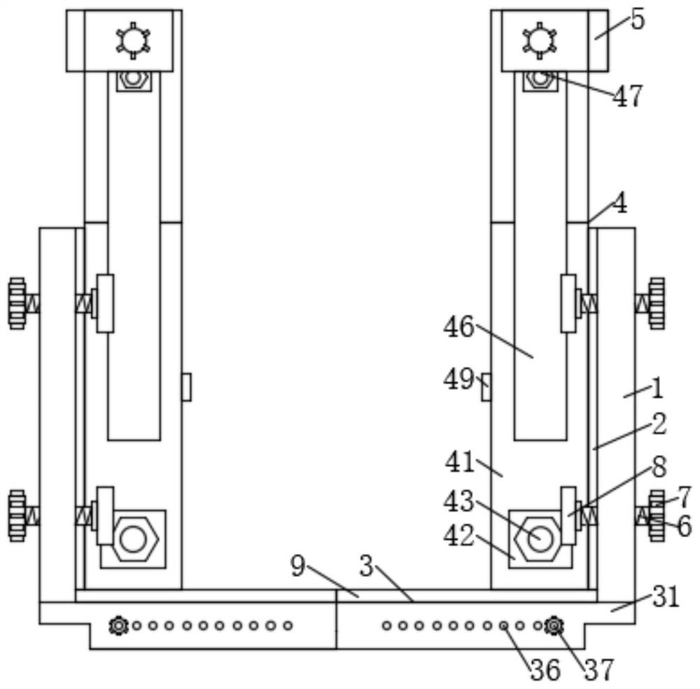
[0026] Example: such as Figure 1-6 As shown, the installation and fixing device of a temperature-controlled optical transmitter in the present invention includes two side plates 1, and rubber plates 2 are fixedly connected to the sides of the two side plates 1 close to each other, and the two sides The lower end of the plate 1 is equipped with a base plate 3, and the rear ends of the two side plates 1 close to each other are fixedly connected with a vertical plate 4, and the upper ends of the vertical plates 4 are equipped with a clamping mechanism 5, and the two side plates 1 are fixedly connected to each other. The bottoms of the front ends of the side plates 1 close to each other are fixedly connected with baffles 9, and the middle parts of the upper and lower ends of the two side plates 1 are all penetrated with screw rods 6, and the screw rods 6 are all threaded on the side plate 1 where they are located. One end of the screw rod 6 located between the sides of the two si...


PUM


Abstract

The invention discloses an installation and fixing device for a temperature-controlled optical transmitter, which comprises two side plates, rubber plates are fixedly connected to the sides where the two side plates are close to each other, and a bottom plate is installed at the lower ends of the two side plates. The rear ends of the two side plates close to each other are fixedly connected with vertical plates, and the upper ends of the vertical plates are equipped with clamping mechanisms. The present invention is a temperature-controlled optical transmitter installation and fixing device, which is used The transmitter is installed on the wall. During installation, the optical cable connected to the temperature-controlled optical transmitter can be conveniently installed on the wall, reducing the space occupied by the temperature-controlled optical transmitter and avoiding affecting the cleaning work of the user. The present invention A vertical plate and a baffle with a clamping mechanism are set on the side plate of the side plate. When in use, use the baffle to clamp the lower end of the optical transmitter, and use the pressure plate of the clamping mechanism to clamp the upper end of the optical transmitter to avoid temperature control. The type optical transmitter is dropped on the ground and is damaged.

Description

technical field [0001] The invention relates to an installation and fixing device, in particular to an installation and fixing device for a temperature-controlled optical transmitter, and belongs to the technical field of temperature-controlled optical transmitters. Background technique [0002] Optical transmitters are commonly used equipment in communications such as broadcast television, telephone, and the Internet. Its function is to convert the HDB3 signal code sent from the multiplexing equipment into NRZ code; then encode the NRZ code into a code pattern suitable for transmission on the optical cable line; finally perform electrical / optical conversion to convert the electrical signal into an optical signal and coupled into the fiber. [0003] At present, when people use the temperature-controlled optical transmitter, most of them directly place the temperature-controlled optical transmitter on the desktop, and the optical cable connected to the temperature-controlled...

Claims


Application Information

Patent Timeline
Patent Type & Authority Patents(China)
IPC IPC(8): H04B10/50F16M11/04F16M13/02
CPCF16M11/04F16M13/02H04B10/50
Inventor 南瑜璇
Owner 南瑜璇
Why Eureka
Try Eureka