A Multi-target Pose Approximation Method for Robot End Based on Joint Angle Compensation

A robot and joint angle technology, applied in the direction of manipulators, program-controlled manipulators, manufacturing tools, etc., can solve problems such as geometric parameter error compensation, absolute pose error, etc., to achieve faster convergence speed, more accurate calculation results, and improved approximation accuracy Effect

Active Publication Date: 2021-06-15
NANJING INST OF TECH
View PDF4 Cites 0 Cited by
  • Summary
  • Abstract
  • Description
  • Claims
  • Application Information

AI Technical Summary

Problems solved by technology

[0004] The purpose of the present invention is to provide a method for approaching the multi-target position and posture of the robot end based on joint angle compensation, which uses the joint angle compensation value instead of compensating geometric parameter errors to control the robot motion, and solves the problem that the robot control system is closed or semi-closed. The user cannot directly compensate the geometric parameter error obtained by identification. At the same time, the objective function built is not only based on the absolute pose error of N target points, but also has a simplified expression form, which is conducive to guiding the search for joints with the objective function as the minimum. The angle correction value is calculated to obtain the joint angle compensation value, and the motion of the robot is controlled to improve the approach accuracy of the multi-target pose at the end of the robot, which can effectively improve the absolute position and attitude accuracy and efficiency of the end of the robot

Method used


Image

  • A Multi-target Pose Approximation Method for Robot End Based on Joint Angle Compensation
  • A Multi-target Pose Approximation Method for Robot End Based on Joint Angle Compensation
  • A Multi-target Pose Approximation Method for Robot End Based on Joint Angle Compensation

Examples


specific Embodiment 1

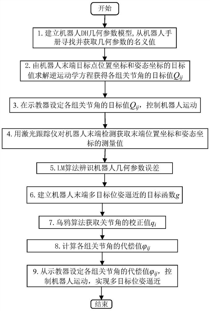
[0106] combine image 3 , the present invention refers to a multi-target pose approaching method based on joint angle compensation at the end of the robot, the method comprising:

[0107] After determining the target value of each group of joint angles according to the nominal value of the robot's geometric parameters, and controlling the movement of each joint of the robot to the target value of each group of joint angles, according to the collected robot end position and attitude data measurement values, the robot geometric parameters The error is identified, and the identified geometric parameter error of the robot is converted into the correction value of each joint angle of the robot. Combined with the correction value of the joint angle obtained through conversion, the compensation of the joint angle used to control the robot to perform the multi-target pose approximation action is calculated. value.

[0108] Preferably, the geometric parameter error of the robot refers ...

specific Embodiment 2

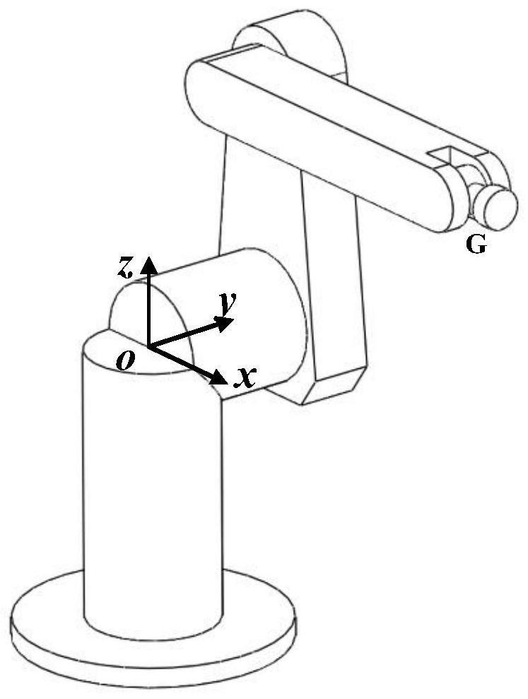
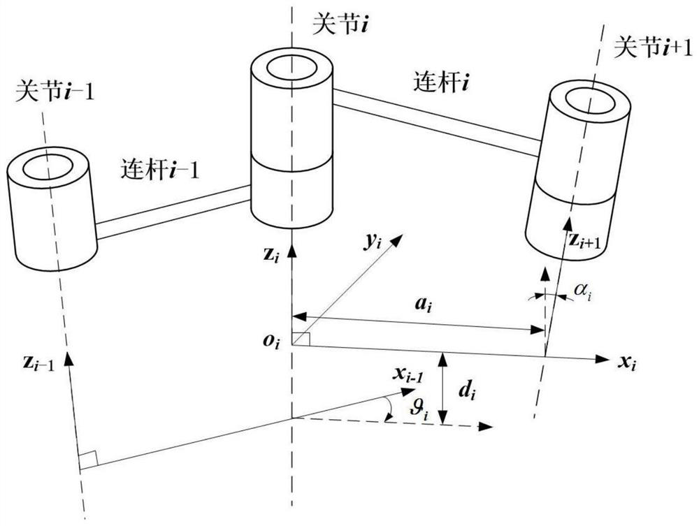
[0112] See figure 1 and figure 2 , figure 1 is a schematic diagram of the serial robot structure, figure 2 is the schematic diagram of the robot DH geometric parameter model. The robot includes a robot base, a first joint, a second joint, ..., an Mth joint and a robot end connected in series in sequence, two adjacent connecting rods are connected through the joint, and the robot base is connected in series with the first joint. connected, the Mth joint is connected in series with the end of the robot.

[0113] Based on the aforementioned robot structure, see image 3 , in this embodiment, the multi-target pose approximation method for the end of the robot based on joint angle compensation specifically includes the following steps:

[0114] Step 1. Establish base coordinate system oxyz and joint coordinate system o i x i the y i z i The following robot DH geometric parameter model, the geometric parameters of the DH geometric parameter model include connecting rod o...

specific Embodiment 3

[0189] Below in conjunction with accompanying drawing, the present invention is described further, as an embodiment of the present invention, what use is Staubli-TX60 six degrees of freedom serial industrial robot, concrete steps are as follows:

[0190] 1. Establish the base coordinate system oxyz and the joint coordinate system o for the Staubli-TX60 six-degree-of-freedom serial robot i x i the y i z i Find and obtain the nominal value of the robot's DH geometric parameter from the robot manual As shown in Table 1, i=1, 2, . . . , M, where M=6.

[0191] Table 1 Nominal values ​​of DH geometric parameters of Staubli-TX60 robot

[0192]

[0193] 2. In order to confirm the correctness of the method of the present invention, the target value p of the 30 target point position coordinates at the end of the Staubli-TX60 robot oj Coordinate component p along the x-axis, y-axis, and z-axis in the base coordinate system oxyz oxj ,p oyj ,p ozj and the target value r of the ...


PUM


Abstract

The invention discloses a method for approaching multi-target poses of a robot terminal based on joint angle compensation, including: determining the target value of each group of joint angles according to the nominal value of the geometric parameters of the robot, and controlling each joint of the robot to move to each group of joints After the target value of the angle is determined, the error of the geometric parameter of the robot is identified according to the measured value of the collected robot end position and attitude data, and the identified error of the geometric parameter of the robot is converted into the correction value of each joint angle of the robot. The correction value of the angle is calculated to obtain the compensation value of the joint angle used to control the robot to perform the multi-target pose approximation action. The invention can use the compensation value of the joint angle instead of compensating the geometric parameter error to control the movement of the robot, which solves the problem that the robot control system is closed or semi-closed, and the user cannot directly compensate the geometric parameter error obtained by identification, and effectively improves the robot terminal. Absolute position and attitude accuracy and efficiency.

Description

technical field [0001] The invention relates to the technical fields of precision measurement and computer application, in particular to a method for approaching multi-target poses at the end of a robot based on joint angle compensation. Background technique [0002] Due to the advantages of fast operation speed, high work efficiency, modular structure design, flexible control system, and high repeatability, robots are playing an increasingly important role in modern life. Today, there are more and more occasions where robots are used to achieve multi-target pose approximation in high-end manufacturing fields such as flexible manufacturing, auxiliary measurement, medical surgery, and aerospace. Its attitude accuracy also puts forward high requirements to realize the high-precision approximation of the robot end to the multi-target pose. The application of robots in the field of high-end manufacturing has also attracted the attention of research institutions at home and abro...

Claims


Application Information

Patent Timeline
Patent Type & Authority Patents(China)
IPC IPC(8): B25J9/16
CPCB25J9/1602B25J9/1628B25J9/1664
Inventor 赵艺兵温秀兰乔贵方吕仲艳崔伟祥姚波
Owner NANJING INST OF TECH
Why Eureka
Try Eureka