
Flexible leading edge structure and design method thereof

A flexible structure and design method technology, applied in the direction of wing adjustment, aircraft parts, ground devices, etc., can solve the problems of discontinuous aerodynamic surface, low reliability, and heavy weight, so as to improve the overall performance of the aircraft and reduce the structural complexity , Improve the effect of deformation accuracy

Active Publication Date: 2020-07-14
CHINA AIRPLANT STRENGTH RES INST
View PDF5 Cites 3 Cited by
  • Summary
  • Abstract
  • Description
  • Claims
  • Application Information

AI Technical Summary

Problems solved by technology

However, there are often gaps in the traditional leading edge flaps, which make the aerodynamic surface discontinuous, increase the friction between the sharp part of the structure and the air, and increase the noise of takeoff and approach landing, and the traditional flaps cannot realize the real-time aerodynamic shape of the full flight envelope. Precise deformation control cannot meet the purpose of real-time optimization of aerodynamic shape
[0003] In order to realize the continuous and precise deformation control of the leading edge of the deformable wing, a variety of continuously variable camber leading edge structures have been proposed at home and abroad, but they are basically based on rigid or semi-rigid structures, which often have complex structures, heavy weight and low reliability issues

Method used


Image

  • Flexible leading edge structure and design method thereof
  • Flexible leading edge structure and design method thereof
  • Flexible leading edge structure and design method thereof

Examples


Embodiment Construction

[0025] In order to make the purpose, technical solution and advantages of the application more clear, the technical solution in the embodiment of the application will be described in more detail below in conjunction with the drawings in the embodiment of the application.

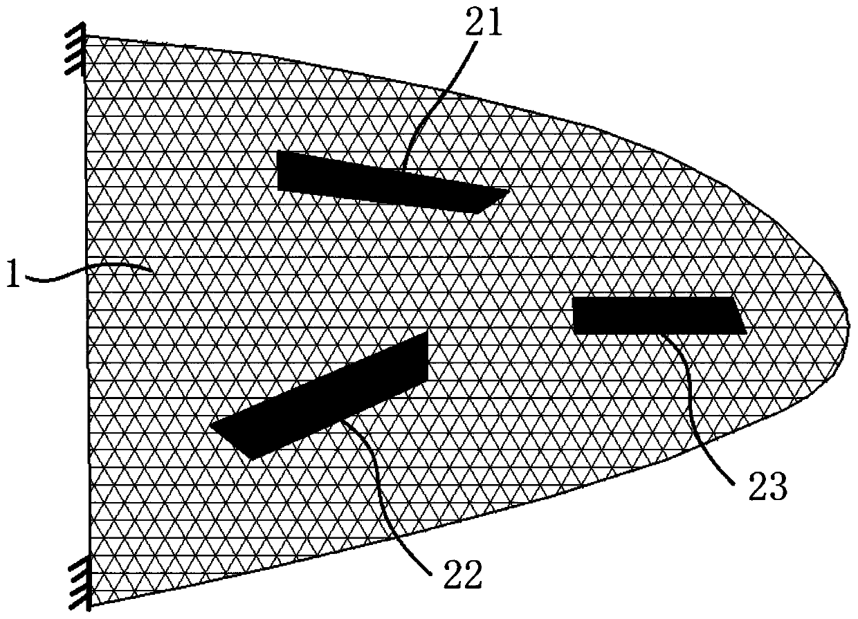
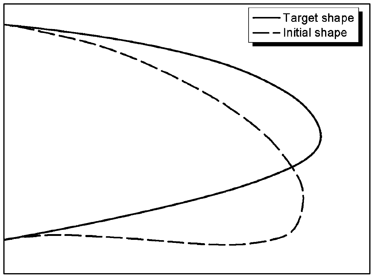
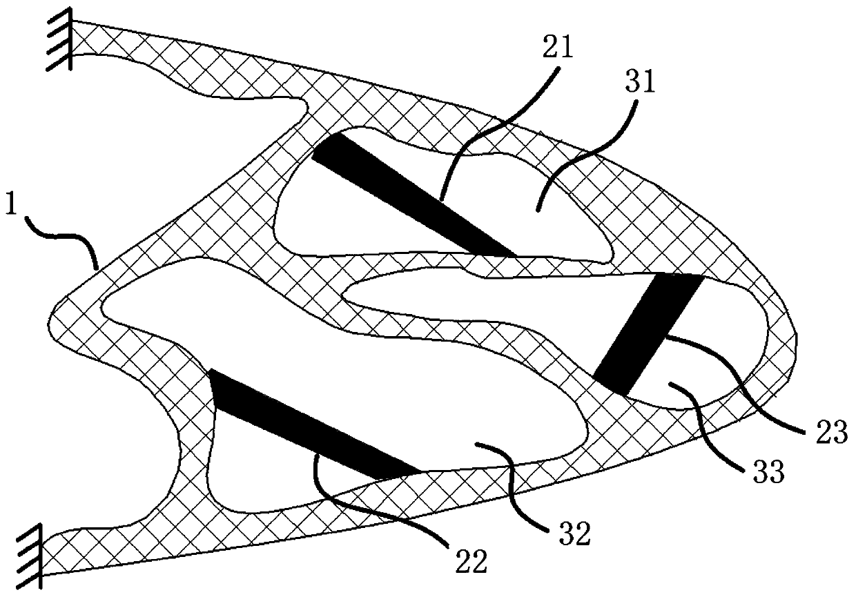
[0026] In order to achieve the seamless, smooth and continuously deformable purpose of the flexible leading edge in the prior art, the present application proposes a flexible leading edge structure based on a distributed driving structure and a design method thereof. In the solution of the present application, by distributing the drive structure inside the flexible structure, the drive structure drives the collaborative optimization of the deformation of the flexible structure to achieve precise control of the aerodynamic shape.

[0027] The flexible leading edge structure provided by this application includes a flexible structure 1 and a plurality of driving structures 21-23. The flexible structure 1 roughly...


PUM


Abstract

The invention provides a flexible leading edge structure. The structure comprises a flexible structure which is used for forming an aerodynamic configuration of a wing leading edge, and driving structures which are arranged in the flexible structure in a distributed mode and can generate driving force under excitation of excitation signals, wherein the driving force acts on the flexible structureto change the aerodynamic configuration of the flexible structure. Compared with an existing variable camber wing leading edge device, the flexible leading edge structure is advantaged in that on onehand, true integration of the structure and functions can be achieved, the driving structure can serve as a driver and can further serve as a bearing structure, structural complexity can be effectively reduced, the weight can be reduced, and comprehensive performance of an airplane can be improved; on the other hand, deformation precision can be improved through the multiple driving mechanisms arranged in a distributed mode, deformation control over the multiple target configurations can be further achieved, and real-time optimization of the front edge configuration is truly achieved.

Description

technical field [0001] The application belongs to the technical field of wing aerodynamic design, and in particular relates to a flexible leading edge structure and a design method thereof. Background technique [0002] The traditional wing can only guarantee the optimal aerodynamic efficiency in the cruising state. In order to meet the aerodynamic requirements in other working conditions, the traditional wing is usually based on the leading edge lift device of the rigid hinge to realize the change and adjustment of the aerodynamic shape. However, there are often gaps in the traditional leading edge flaps, which make the aerodynamic surface discontinuous, increase the friction between the sharp part of the structure and the air, and increase the noise of takeoff and approach landing, and the traditional flaps cannot realize the real-time aerodynamic shape of the full flight envelope. Precise deformation control cannot meet the purpose of real-time optimization of aerodynamic...

Claims


Application Information

Patent Timeline
Patent Type & Authority Applications(China)
IPC IPC(8): B64C3/50B64F5/00
CPCB64C3/50B64F5/00Y02T90/00
Inventor 王志刚杨宇
Owner CHINA AIRPLANT STRENGTH RES INST
Learn More