Mechanical-electrical integrated device for keeping constant temperature of dyeing solution
A technology of constant temperature and dye liquor, applied in the direction of processing textile material equipment configuration, etc., can solve problems such as easy to reduce dyeing quality, and achieve the effect of ensuring accuracy and improving quality
- Summary
- Abstract
- Description
- Claims
- Application Information
AI Technical Summary
Problems solved by technology
Method used
Image

Examples
Embodiment 1
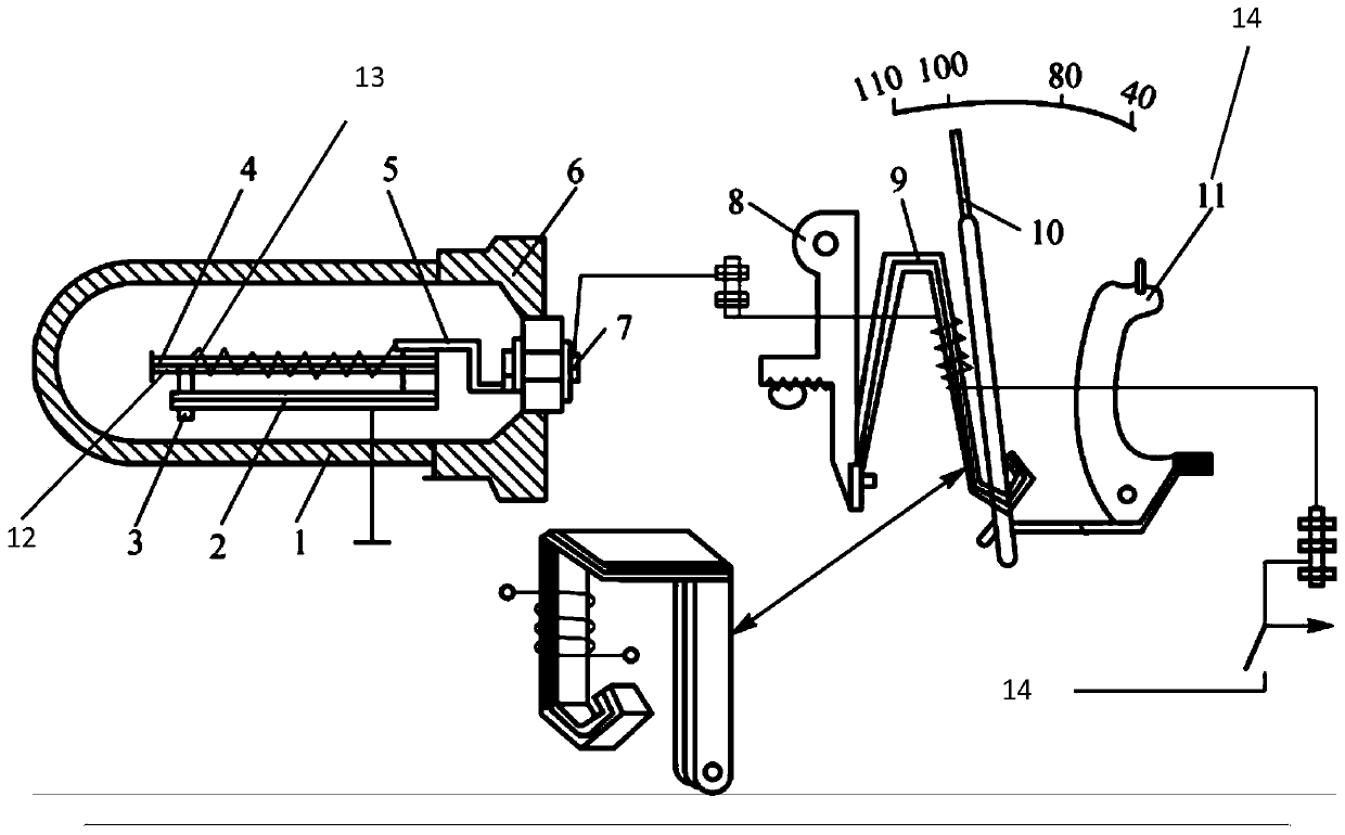
[0022] Embodiment 1, a kind of mechatronics device for constant temperature of dye liquor, comprises heating plate 9 and thermometer 10:
[0023] Such as figure 1 As shown, the thermometer 10 is provided with a connection mechanism 15 fixedly connected thereto. The connection mechanism 15 includes a connection bracket, the connection bracket is fixedly connected with the heating sheet 9, and the heating sheet 9 is provided with a surrounding heating coil 7, and the heating coil 7 One end is electrically connected to the power supply 14, and the other end is provided with a temperature control mechanism 1 electrically connected thereto. The connecting bracket includes a first fixed block 11 and a second fixed block 8, the first fixed block 11 is fixedly connected to the thermometer 10, and the second The fixed block 8 is fixedly connected with the heating plate 9, and the thermometer 10 is used to detect the temperature of the dye solution when the heating plate 9 is working. ...
Embodiment 2
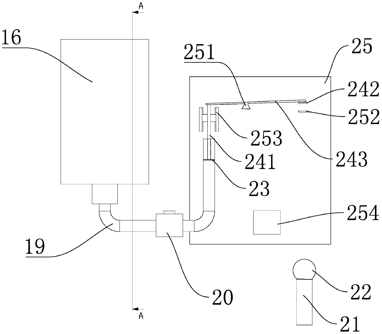
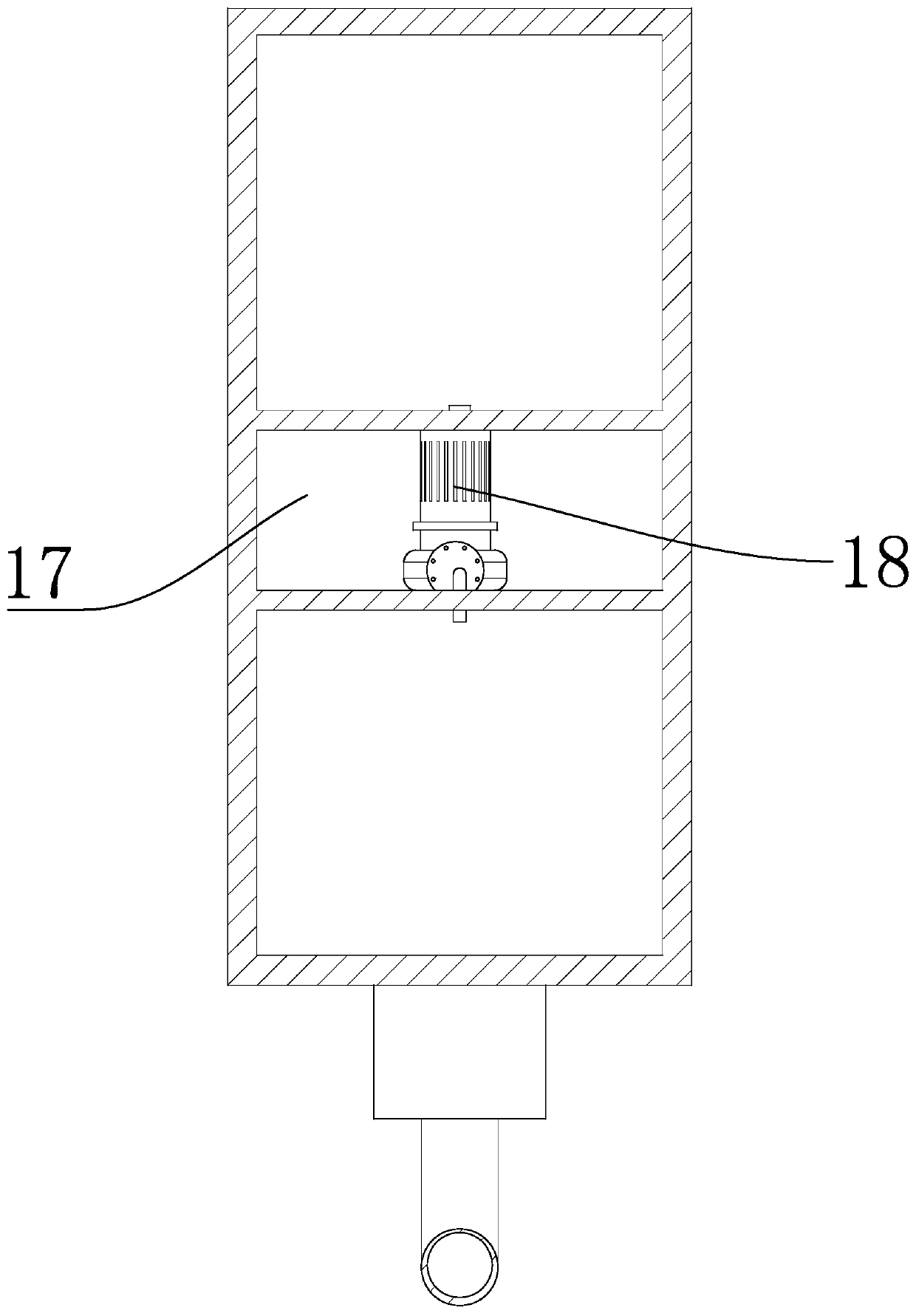
[0029] Embodiment 2 is different from Embodiment 1 in that the temperature control mechanism 1 also includes a bottom plate 25 and a liquid storage tank 16, and the liquid storage tank 16 is provided with an independent driving layer 17, and a small bidirectional pump 18 is fixedly connected to the driving layer 17. One end of the small two-way pump 18 communicates with the upper layer of the liquid storage tank 16, and the other end communicates with the lower layer of the liquid storage tank 16. The lower layer of the liquid storage tank 16 is provided with a U-shaped pipeline 19 communicating with it. The U-shaped pipeline 19 is fixedly connected with a solenoid valve 20 , the end away from the liquid storage barrel 16 is provided with a floating block 23, and the floating block 23 is provided with a linkage component 24.
[0030] Such as figure 2 As shown, the linkage part 24 includes a push rod 241. One end of the push rod 241 is fixedly connected with the floating block...
PUM
 Abstract
Description
Claims
Application Information