Sealing device used for cryogenic ball valve

A technology for sealing devices and ball valves, applied to valve devices, cocks including cut-off devices, engine components, etc., can solve problems such as leakage of low-temperature ball valves, and achieve the effects of preventing leakage, good low-temperature sealing, and increasing contact force

Pending Publication Date: 2020-07-14
上海华托阀门自动化有限公司
View PDF0 Cites 2 Cited by
  • Summary
  • Abstract
  • Description
  • Claims
  • Application Information

AI Technical Summary

Problems solved by technology

[0005] Aiming at the problem that the existing cryogenic ball valve may leak under low temperature conditions, the p...

Method used


Image

  • Sealing device used for cryogenic ball valve
  • Sealing device used for cryogenic ball valve
  • Sealing device used for cryogenic ball valve

Examples


Embodiment 1

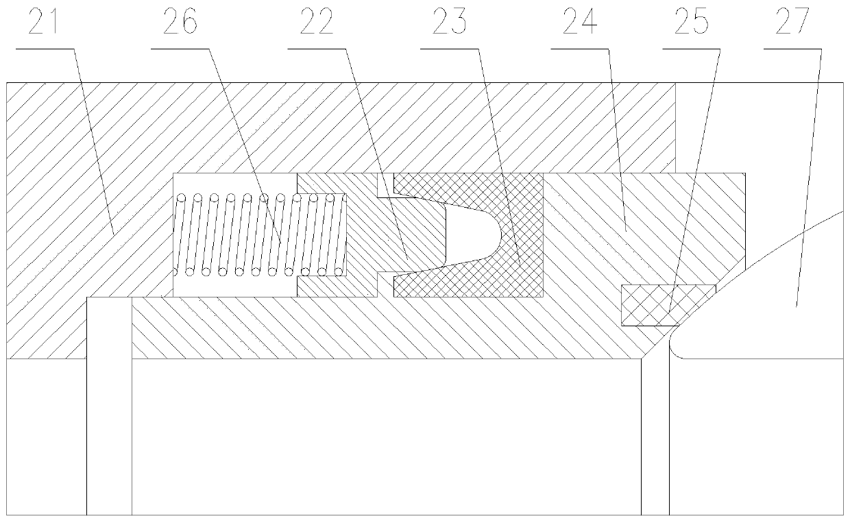
[0032] A sealing device for cryogenic ball valves, see figure 2 , including a valve body 21, a metal valve seat 24 and a ball 27, an annular metal support ring 22 and an annular first lip seal 23 are installed in the space between the valve body 21 and the metal valve seat 24, and the first lip seal The ring 23 includes two first lips, and there is an annular groove between the first lips. The outside of the first lip seal 23 is pressed against the valve body 21, and the inside of the first lip seal 23 is in contact with the metal valve seat. 24 against pressure. One end of the metal support ring 22 is a protruding head, and the other end of the metal support ring 22 is a set of round holes, the protruding head abuts against the annular groove of the first lip seal 23 . A thrust spring 26 is arranged in a group of circular holes of the metal support ring 22 , and the other end of the thrust spring 26 is against the valve body 21 .

[0033]The thrust spring 26 pushes the met...

Embodiment 2

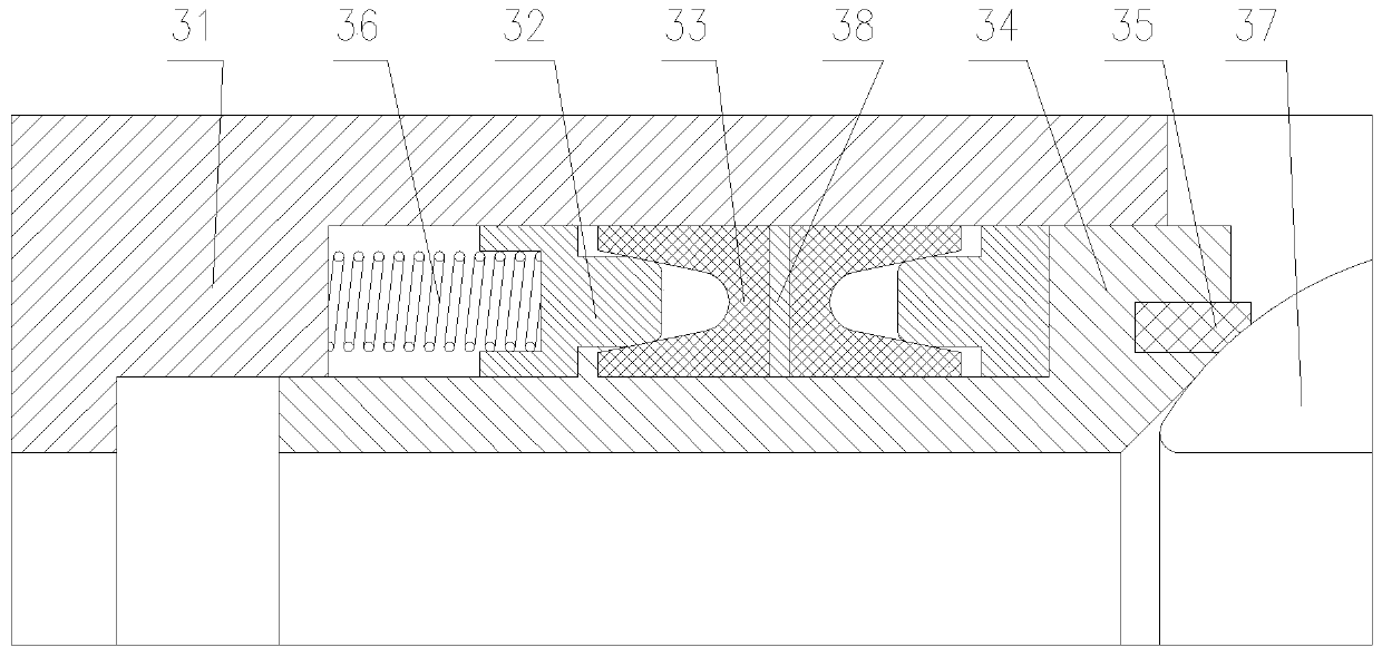
[0035] A sealing device for cryogenic ball valves, which is a double-piston effect sealing structure, see image 3 , including a valve body 31, a metal valve seat 34 and a ball 37, an annular metal support ring 32 and an annular first lip seal 33 are installed in the space between the valve body 31 and the metal valve seat 34, the first lip seal The ring 33 includes two first lips, and there is an annular groove between the first lips. The outside of the first lip seal 33 is pressed against the valve body 31, and the inside of the first lip seal 33 is in contact with the metal valve seat. 34 against pressure. One end of the metal support ring 32 is a protruding head, and the other end of the metal support ring 32 is a set of round holes, the protruding head abuts against the annular groove of the first lip seal 33 . A thrust spring 36 is arranged in a group of round holes of the metal support ring 32 , and the other end of the thrust spring 36 is against the valve body 31 , a...

Embodiment 3

[0038] A sealing device for a cryogenic ball valve is a secondary sealing structure, including a first lip seal ring 43 with a first toe heel 411, providing a secondary sealing structure of axial sealing and plane sealing. see Figure 4 , including a valve body 41, a ball 47, a metal valve seat 44, a first lip seal 43 with a first toe heel 411 in the annular cavity of the valve body 41 and the metal valve seat 44, a metal support ring 42, and a protruding head part against the annular groove of the first lip seal ring 43 with the first toe heel 411, pushed by a group of thrust springs 46 on the back, and the outer side of the first lip tightly pushes against the inner cylinder surface inside the valve body 41, There is a notch on the valve body 41, the first toe heel 411 is pressed on the notch, the lip seal seat 43 with the first toe heel 411 is pressed by a pressing plate 49, and the pressing plate 49 is pressed on the valve body 41 with a screw 48 On the front end of the m...


PUM


Abstract

The invention provides a sealing device for a cryogenic ball valve. The sealing device comprises a valve body, a metal valve seat and a sphere; an annular metal support ring and an annular first lip sealing ring are installed in a space between the valve body and the metal valve seat; the first lip sealing ring includes two first lip edges; an annular groove is formed between the first lip edges;the outer side of the first lip sealing ring butts against the valve body; the inner side of the first lip sealing ring is butts against the metal valve seat; one end of the metal support ring is a protruding head part; the other end of the metal support ring is a circular hole; the protruding head part butts against the interior of the annular groove of the first lip sealing ring; a thrust springis arranged in the circular hole of the metal support ring; and the other end of the thrust spring butts against the valve body. The sealing device for the cryogenic ball valve provided by the invention has very good low-temperature sealing performance.

Description

technical field [0001] The invention belongs to the technical field of sealing valve seats of cryogenic ball valves, and in particular relates to a sealing device for cryogenic ball valves. Background technique [0002] For fixed ball valves used in cryogenic liquids such as liquid oxygen, liquid nitrogen, liquefied natural gas (LNG) or other cryogenic media, the traditional sealing seat adopts the first lip seal ring with a standard PTFE plastic built-in metal spring, which is called Lip seal. To prevent leakage between the metal seat and the valve body. This structure leaks when the temperature drops to -75°C or lower. The requirements for sealing are becoming more and more difficult, so that the technical standards formulated at home and abroad also allow leakage at a low temperature of -196°C. Does not meet bubble level "zero" leakage requirements. [0003] figure 1 It is the traditional sealing structure of cryogenic ball valve. Valve body 11, first lip seal ring ...

Claims


Application Information

Patent Timeline
IPC IPC(8): F16K5/06F16K5/20
CPCF16K5/0678F16K5/0689F16K5/202
Inventor 邬佑清邬挺之黄永萍
Owner 上海华托阀门自动化有限公司
Why Eureka
Try Eureka