Power supply system of communication equipment and control method thereof

A technology for communication equipment and power supply system, which is applied in the direction of control/regulation system, electrical components, circuit devices, etc., can solve the problems that the power supply system cannot meet the requirement of proportional sharing of power supply links, the power supply of communication equipment is inflexible, and the efficiency of the power supply system is low. , to make up for the insufficient number of input power supply terminals, improve maintainability, and improve the power supply load rate.

Active Publication Date: 2020-07-14
FENGHUO COMM SCI & TECH CO LTD
View PDF6 Cites 5 Cited by
  • Summary
  • Abstract
  • Description
  • Claims
  • Application Information

AI Technical Summary

Problems solved by technology

[0006] The purpose of the present invention is to provide a communication equipment power supply system and its control method, so that it can solve the problem of inflexible power supply in the communication equipment, many power fragments in the application, low efficiency of the power supply system, and the inability of the power supply system to realize power supply in the prior art. Link ratio allocation requirements, inconvenient activation and maintenance, etc.

Method used


Image

  • Power supply system of communication equipment and control method thereof
  • Power supply system of communication equipment and control method thereof
  • Power supply system of communication equipment and control method thereof

Examples


Embodiment 1

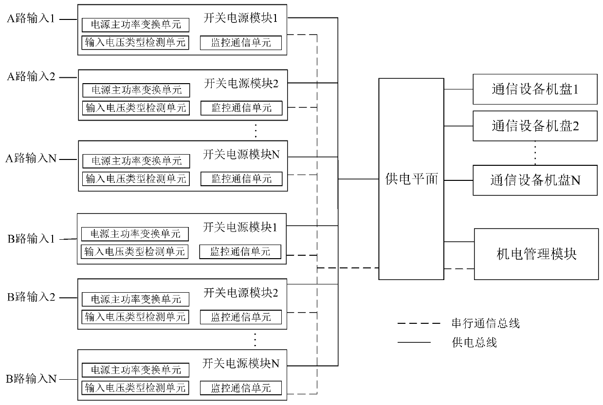
[0055] like figure 1 As shown in , it is a schematic structural diagram of a communication device power supply system provided by an embodiment of the present invention. The power supply system includes an electromechanical management module, a power supply plane, and at least 2N switching power supply modules (N≥1).

[0056] Wherein, the number of switching power supply modules input by the A channel is equal to the number of switching power supply modules input by the B channel.

[0057] The DC outputs of the N switching power supply modules input by the A channel are connected to the power supply plane, and the N switching power supply modules input by the A channel are connected by serial communication signals.

[0058] The DC outputs of the N switching power supply modules input by the B-channel are connected to the power supply plane, and the N switching power supply modules input by the B-channel are connected by serial communication signals.

[0059] The DC outputs o...

Embodiment 2

[0074] This embodiment provides a solution for the electromechanical management module to determine the load distribution plan of each switching power supply module according to the operating status, input voltage type and physical slot information of each switching power supply module, specifically:

[0075] The calculation relationship of the distribution ratio of the power supply system undertaken by the input power of the A line and the B line is as follows:

[0076] D. A ﹦﹙N﹣M A ﹚ / ﹝2N﹣(M A +M B )﹞;

[0077] D. B ﹦﹙N﹣M B ﹚ / ﹝2N﹣(M A +M B )﹞;

[0078] In the formula, D A 、D B Respectively, the ratio of the power supply of the input power supply of the A channel and the B channel;

[0079] N is the number of normal operation of the switch modules configured in the power supply system detected by the electromechanical management module;

[0080] m A , M B are respectively the number of normal operating switching power supply modules whose A-way and B-way inputs a...

Embodiment 3

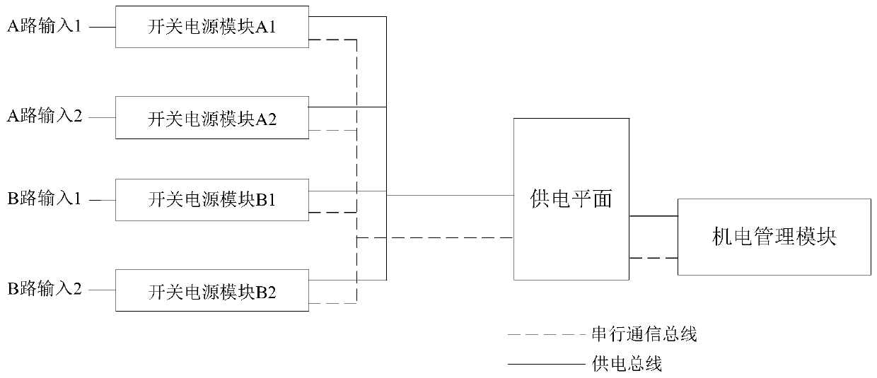
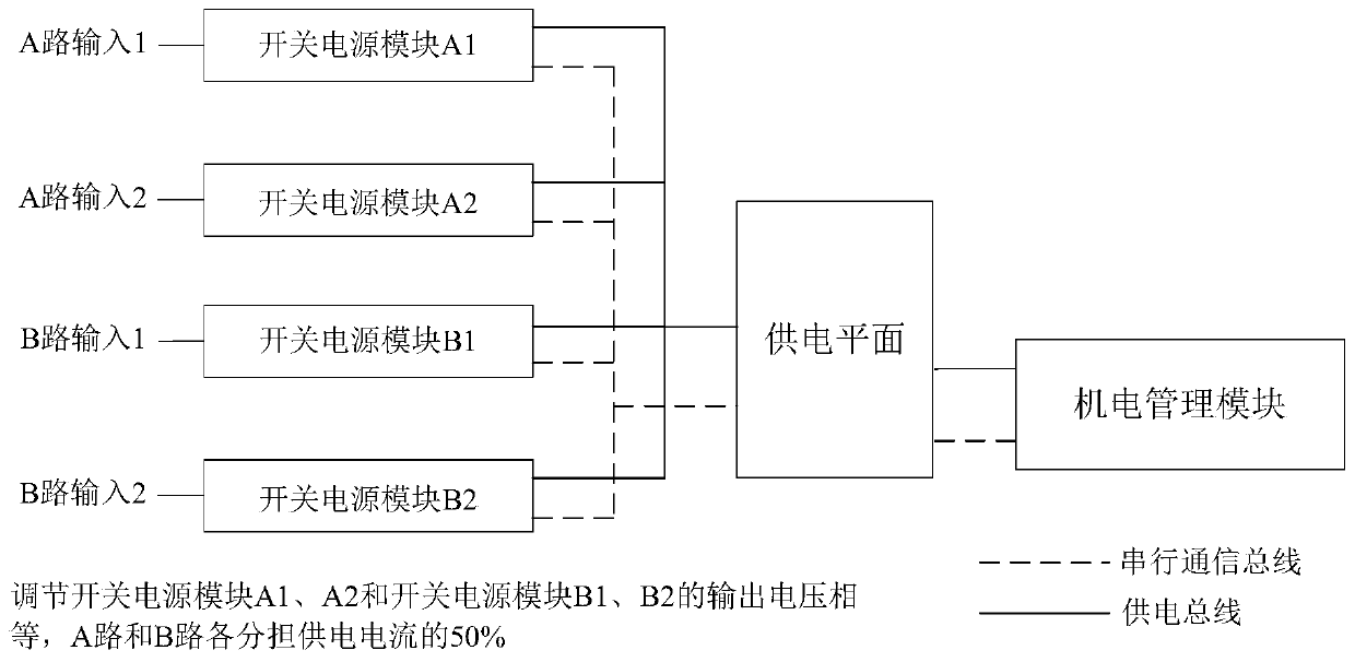
[0085] like figure 2 As shown in FIG. 2 , it is a schematic diagram of application of proportional distribution of a power supply system for communication equipment provided by an embodiment of the present invention. The power supply system adopts 2+2 redundant power supply, that is, the power supply terminals provided by the power distribution cabinet are 2+2 lines, and the number of switching power supply modules in the power supply system is 2+2.

[0086] The communication equipment in the power supply system is powered by the only power supply plane. Through the output voltage adjustment technology of the switching power supply module, the output voltage of the switching power supply module in the power supply system is adjusted to provide different current carrying values ​​of the main / standby power supply of the power distribution cabinet. So as to meet the requirements of AC direct supply in the IDC computer room or the power supply requirements of power supply cutting...


PUM


Abstract

The invention discloses a power supply system of communication equipment. The system comprises an electromechanical management module, a power supply plane and at least 2N switching power supply modules, wherein an input voltage type detection unit in each switching power supply module is used for detecting the type of a voltage accessed to the switching power supply module, detecting the physicalslot position information of the switching power supply module in a power supply plane, and reporting the type of the input voltage, the physical slot position information and the operation state information of the switching power supply module to the electromechanical management module; the electromechanical management module is used for determining a load distribution plan of each switching power supply module and issuing an output voltage regulation command to the corresponding switching power supply module according to the load distribution plan; and each switching power supply module changes the duty ratio of the driving power conversion circuit according to the received output voltage adjustment command so as to adjust the magnitude of the DC output voltage. The power supply systemis flexible in power supply and high in power supply efficiency. The invention further provides a control method of the communication equipment power supply system.

Description

technical field [0001] The invention belongs to the technical field of power supply for communication equipment, and more specifically relates to a power supply system for communication equipment and a control method thereof. Background technique [0002] Usually, in order to ensure the reliability of the communication equipment power supply system, in addition to the N (N ≥ 1) main switching power supply modules for normal power supply in the actual application of communication equipment, the same number of N (N ≥ 1) standby switching power supply modules will also be introduced. Switching power supply module, 2N switching power supply modules are introduced into the communication equipment and the number of power supply terminals to be provided in the computer room is also 2N. The communication equipment uses N or 2N partition planes to supply power to all the machine disks in the communication equipment. [0003] The communication equipment adopts N+N redundant backup mod...

Claims


Application Information

Patent Timeline
Patent Type & Authority Applications(China)
IPC IPC(8): H02J1/10H02J9/06H02M3/00H02M7/02
CPCH02J1/102H02J9/061H02M3/00H02M7/02
Inventor 舒有进徐云中杨嗣珵
Owner FENGHUO COMM SCI & TECH CO LTD
Why Eureka
Try Eureka