Adjustable axial positioning device of lathe

A technology for axial positioning and lathes, applied in the field of machinery, can solve the problems of worn spindle holes, lack of versatility, high cost of positioning fixtures, etc., and achieve the effects of fast and accurate axial positioning, compact structure, and convenient operation

Inactive Publication Date: 2020-07-17
SHENYANG AIRCRAFT CORP
View PDF10 Cites 1 Cited by
  • Summary
  • Abstract
  • Description
  • Claims
  • Application Information

AI Technical Summary

Problems solved by technology

[0002] When machining parts on a lathe, axial positioning is often required. In actual production, there are mainly two methods for axial positioning of lathes: one is to directly clamp the part with a three-jaw chuck, and adjust the axial dimension through single-piece measurement. The first method needs to be re-measured and adjusted every time the clamping is performed, which not only has a lot of repetitive workload and low efficiency, but also has measurement errors in each measurement and poor positioning accuracy; the other is to make it separately in advance according to the shape and axial positioning of the processed parts. Although the positioning fixture can meet the positioning requirements, the cost of making the positioning fixture is high and the efficiency is low
[0003] After retrieval, the multi-purpose axial positioning gear plate described in the authorized announcement number CN 209565856 U realizes axial positioning through the stepped shaft and steel balls on the gear plate, but the axial positioning size is not adjustable and lacks versatility; authorized announcement number CN204277596 A kind of CNC lathe spindle positioning structure described in U is fixed by the cooperation of the Morse cone and the spindle taper hole. There is a threaded hole in the middle of the Morse cone, and the screw passes through the threaded hole to connect with the Morse cone. Relative to the protruding length of the Morse cone, the axial positioning dimension of the processed part can be adjusted. Although the patent can realize the adjustable axial positioning, but because the positioning structure is installed inside the main shaft, the chuck needs to be disassembled for each loading and unloading, and the operation is cumbersome. , low efficiency, and its Morse cone is in contact with the spindle hole, repeated disassembly will wear the spindle hole and reduce the accuracy of the machine tool

Method used


Image

  • Adjustable axial positioning device of lathe
  • Adjustable axial positioning device of lathe
  • Adjustable axial positioning device of lathe

Examples


Embodiment Construction

[0025] The specific embodiments of the present invention will be described in further detail below in conjunction with the accompanying drawings, so as to help those skilled in the art have a more complete and in-depth understanding of the present invention.

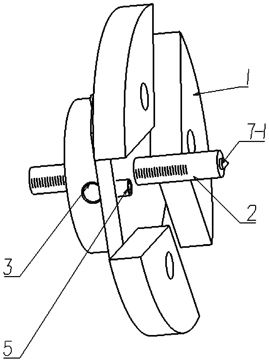
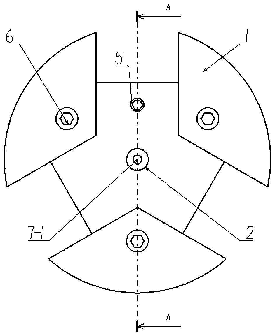
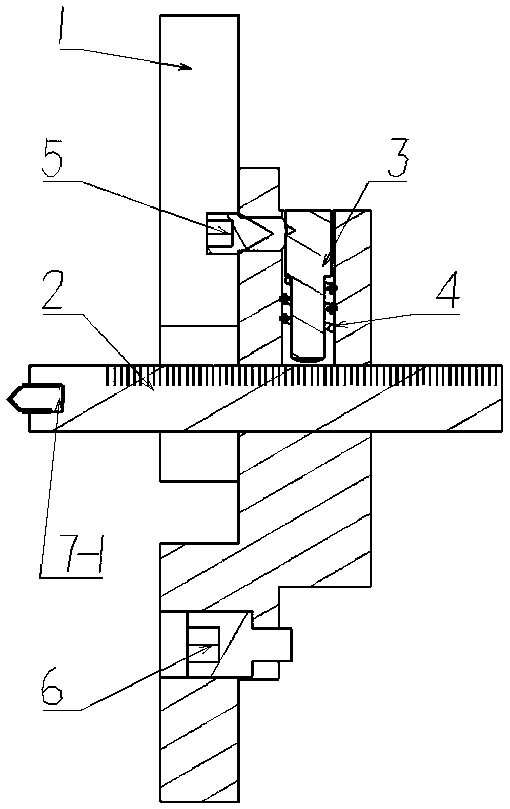
[0026] like figure 1 and Figure 5 As shown, an adjustable axial positioning device for a lathe includes a main body plate 1, a positioning rod 2, a clamping pin 3, a spring 4, a locking screw 5, a fastening bolt 6 and a positioning cap.

[0027] According to the positioning needs of the processed parts, select the required positioning cap: when processing slender rod parts that require top positioning, select the positioning cap A7-1, and connect the external thread of the positioning cap A7-1 with the internal thread hole 2 of the positioning rod -2 is connected through thread fitting; when processing large-diameter parts that require end face positioning, select the positioning cap B7-2, and connect the internal thre...


PUM


Abstract

The invention discloses an adjustable axial positioning device of a lathe, and belongs to the technical field of machines. The adjustable axial positioning device of the lathe comprises a main body disc, a positioning rod, a clamping pin, a spring, a locking screw, a fastening bolt and a positioning cap. According to the adjustable axial positioning device of the lathe, the positioning cap is replaced, so that the positioning requirements of parts of different structures can be met; the fastening bolt is connected with a three-jaw chuck of the lathe, so that the device can be disassembled without disassembling the three-jaw chuck, the operation is convenient, and the labor is saved; and the fastening screw is adjusted through a small stroke, the tightness and the loosening of the positioning rod is realized through the cooperation of the spring force and the conical surface, the adjustment of axial positioning is completed, the structure is exquisite, and the operation is simple.

Description

technical field [0001] The invention belongs to the technical field of machinery and relates to a lathe processing auxiliary tool, in particular to an adjustable axial positioning device for a lathe. Background technique [0002] When machining parts on a lathe, axial positioning is often required. In actual production, there are mainly two methods for axial positioning of lathes: one is to directly clamp the part with a three-jaw chuck, and adjust the axial dimension through single-piece measurement. The first method needs to be re-measured and adjusted every time the clamping is performed, which not only has a lot of repetitive workload and low efficiency, but also has measurement errors in each measurement and poor positioning accuracy; the other is to make it separately in advance according to the shape and axial positioning of the processed parts. Although the positioning fixture can meet the positioning requirements, the cost of making the positioning fixture is high a...

Claims


Application Information

Patent Timeline
IPC IPC(8): B23Q3/18
CPCB23Q3/18
Inventor 孙捷夫潘海薛祥友
Owner SHENYANG AIRCRAFT CORP
Why Eureka
Try Eureka