
A hydraulic vibration system

An oscillating system and hydraulic technology, applied in vibration generating devices, fluid pressure actuating devices, wellbore/well components, etc., can solve the problems of difficult processing, limited vibration impact momentum, high cost, etc., and reduce the number of trips , high oscillation frequency, and the effect of reducing drilling costs

Active Publication Date: 2021-11-19
NORTHEAST GASOLINEEUM UNIV
View PDF18 Cites 0 Cited by
  • Summary
  • Abstract
  • Description
  • Claims
  • Application Information

AI Technical Summary

Problems solved by technology

[0005] The purpose of the present invention is to provide a hydraulic oscillation system, which is used to solve the problems of limited vibration impact momentum, difficult processing and high cost in the current method of using hydraulic power to generate radial vibration

Method used


Image

  • A hydraulic vibration system
  • A hydraulic vibration system
  • A hydraulic vibration system

Examples


Embodiment Construction

[0033] Below in conjunction with accompanying drawing, the present invention will be further described:

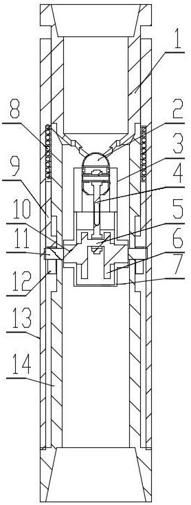
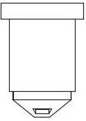
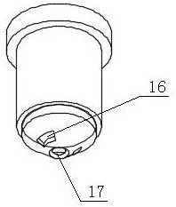
[0034] Such as figure 1 As shown, this hydraulic oscillation system includes an upper sleeve 1, a piston 2, an upper cylinder liner 3, a lower cylinder liner 7, a crankshaft 5, a connecting rod 4, a balance flywheel 6, an outer edge shaft 10, a camshaft 11, a cam 12, Push rod 9, ring wall spring 8, oscillating outer sleeve 13, lower connecting sleeve 14, the lower connecting sleeve 14 is threadedly connected to the lower end of the upper connecting sleeve 1 to form an inner cylinder, the lower end of the lower connecting sleeve 14 has an annular step outside, and the oscillating outer sleeve 13 surrounds it Out of the tube and freely fall on the annular step, the oscillating jacket 13 is socketed with the entire internal system; the oscillating jacket 13 forms an annular space with the lower connecting tube 14 through the inner step set on the upper part, and the upper por...


PUM


Abstract

The invention relates to a hydraulic oscillation system, which includes an upper joint, a piston, a crankshaft, a connecting rod, and a balance flywheel. The lower joint is connected with the upper joint to form an inner cylinder. On the steps, the oscillating outer casing and the lower socket form an annular space; the upper cylinder liner and the lower cylinder liner are sealed and connected, the piston slides along the inner wall of the upper cylinder liner, and the hemispherical head of the piston is in contact with the hemispherical flow port at the bottom of the upper socket. The upper end of the connecting rod is connected to the piston, and the lower end of the connecting rod is connected to the crankshaft. The crankshaft is located in the lower cylinder liner. The balance flywheel is fixed at both ends of the crankshaft. The outer edge shaft is fixed outside the balance flywheel. The camshafts are connected, and the camshafts all pass through the limit holes of the lower socket and are located in the annular space. The camshafts are equipped with cams, the push rods freely fall on the cams, and the ring wall springs freely fall on the push rods. The invention can generate stable axial vibration, and reduce damage to other parts caused by vibration while improving the rock-breaking efficiency of the drill bit.

Description

technical field [0001] The invention relates to a drilling device used in the fields of petroleum engineering, mining engineering, geotechnical engineering and the like, and in particular relates to a hydraulic oscillation system. Background technique [0002] In order to meet the needs of the development of oil and gas exploration, contemporary oil drilling is mainly extended to deep and complex blocks. With the development of major oilfields, more and more wells with complex structures such as highly deviated wells, horizontal wells and multi-branch horizontal wells are used. The frictional resistance between the column and the borehole wall is increasing, resulting in low drilling weight transmission efficiency, which seriously restricts the drilling speed and extension ability. In the process of deep well drilling, the problems of difficult drilling in hard formations and slow drilling speed are very prominent. In order to meet the needs of new drilling conditions or n...

Claims


Application Information

Patent Timeline
Patent Type & Authority Patents(China)
IPC IPC(8): E21B28/00F15B15/14F15B15/20
CPCE21B28/00F15B15/1428F15B15/1447
Inventor 李思琪田胜雷凌鑫李玮李卓伦李梅
Owner NORTHEAST GASOLINEEUM UNIV
Learn More