Shield tail brush dynamic sealing pressure resistance test equipment
What is Al technical title?
Al technical title is built by PatSnap Al team. It summarizes the technical point description of the patent document.
A dynamic sealing and pressure test technology, which is used in the testing of wear resistance, mechanical parts testing, machine/structural parts testing, etc. Problems such as unable to dynamically render
Pending Publication Date: 2020-07-17
昆山众备机械设备有限公司
View PDF0 Cites 4 Cited by
Summary
Abstract
Description
Claims
Application Information
AI Technical Summary
This helps you quickly interpret patents by identifying the three key elements:
Problems solved by technology
Method used
Benefits of technology
Problems solved by technology
[0003] With the development of urban construction in our country, underground rail transit, cross-river tunnels and other underground projects are increasing day by day, and the shield tunneling distance is getting longer and longer. Strictly, the pressure-resistant sealing performance of the shield tail seal brush directly affects the sealing safety of the construction process. At present, there is no uniform testing standard for the pressure resist
Method used
Image
Click on the blue label to locate the original text in one second.
Reading with bidirectional positioning of images and text.
Examples
Embodiment
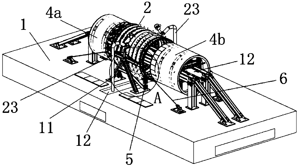
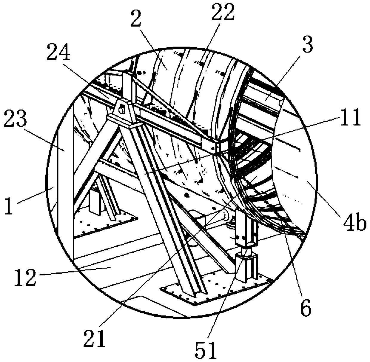
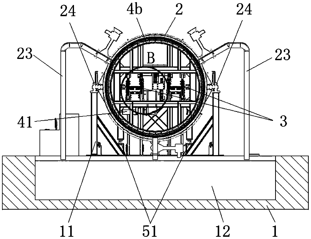
[0029] like figure 1 and figure 2 As shown, a shield tail brush dynamic seal pressure resistance test equipment of the present invention includes a base 1, a support frame 11 straddling the middle of the base 1, a simulated shield tail steel cylinder 2 pivotally connected above the support frame 11, The transmission track 3 horizontally passing through the axial hollow of the simulation shield tail steel cylinder 2 and the simulation segment 4a and self-sealing steel cylinder 4b that can move along the transmission track 3, the simulation segment 4a and the self-sealing steel cylinder 4b are separated on the The two sides of the simulated shield tail steel cylinder 2, the outer diameters of the simulated segment 4a and the self-sealing steel cylinder 4b are smaller than the inner diameter of the simulated shield tail steel cylinder 2, and the axes of both are the same as the axis of the simulated shield tail steel cylinder 2 when it is horizontal. line, the inner wall of the...
PUM
Abstract
The invention belongs to the technical field of test equipment, and relates to shield tail brush dynamic sealing pressure resistance test equipment. The equipment comprises a base, a support frame spanning the middle part of the base, a simulated shield tail steel cylinder pivoted above the support frame, a transmission track horizontally penetrating through the axial hollow part of the simulatedshield tail steel cylinder, and a simulated segment and a self-sealing steel cylinder which can move along the transmission track, wherein the simulated segment and the self-sealing steel cylinder arerespectively disposed at two sides of the simulation shield tail steel cylinder. The outer diameters of the simulated segment and the self-sealing steel cylinder are smaller than the inner diameter of the simulation shield tail steel cylinder, and the axes of the simulated segment and the self-sealing steel cylinder are collinear with the horizontal axis of the simulation shield tail steel cylinder; the inner wall of the simulation shield tail steel cylinder is provided with a plurality of oil receiving ring grooves used for installing shield tail brushes in a mirror symmetry mode, the innersides of the oil receiving ring grooves are communicated with a plurality of pressure sensors, and the bottom of the simulation shield tail steel cylinder is provided with a segment gap adjusting device used for adjusting the angle. The structure can simulate the dynamic process of the shield tunneling machine, and can test the wear resistance and dynamic sealing performance of the shield tail brush at the same time.
Description
technical field [0001] The invention relates to the technical field of testing equipment, in particular to a shield tail brush dynamic sealing pressure-resistant testing equipment. Background technique [0002] Shield machine, the full name is shield tunnel boring machine, is a kind of special engineering machinery for tunnel boring. Modern shield boring machine integrates light, machinery, electricity, hydraulic, sensing and information technology, and has the ability to excavate and cut soil. Body, rock, soil ballast conveying, tunnel lining assembly, measurement guidance and deviation correction, etc., involving geology, civil engineering, machinery, mechanics, hydraulics, electricity, control, measurement and other disciplines and technologies, and "tailor-made" according to different geology Type design and manufacture, high reliability requirements. Shield boring machines have been widely used in subway, railway, highway, municipal, hydropower and other tunnel project...
Claims
Application Information
Patent Timeline
Application Date:The date an application was filed.
Publication Date:The date a patent or application was officially published.
First Publication Date:The earliest publication date of a patent with the same application number.
Issue Date:Publication date of the patent grant document.
PCT Entry Date:The Entry date of PCT National Phase.
Estimated Expiry Date:The statutory expiry date of a patent right according to the Patent Law, and it is the longest term of protection that the patent right can achieve without the termination of the patent right due to other reasons(Term extension factor has been taken into account ).
Invalid Date:Actual expiry date is based on effective date or publication date of legal transaction data of invalid patent.