Anchor Chain Observation Tool

A technology of tooling and anchor chains, which is applied in the field of ships, can solve the problems of the risk of falling into the water, the inability to retract the anchor chains, and the large angle of the anchor chains, etc., to achieve the effects of smooth retraction, simple structure, and low cost.

Active Publication Date: 2022-05-10
CSSC HUANGPU WENCHONG SHIPBUILDING COMPANY
View PDF7 Cites 0 Cited by
  • Summary
  • Abstract
  • Description
  • Claims
  • Application Information

AI Technical Summary

Problems solved by technology

The choice of anchorage needs to refer to the water flow and wind direction, and it is necessary to continuously observe the state, orientation, angle, etc. of the anchor chain to judge the relative displacement and state between the ship and the anchor point. If the observation is neglected, the anchor chain often scratches the ball The hull structure such as the nose bow may even cause the anchor chain angle to be too large so that the anchor chain cannot be retracted
In the traditional observation method, the anchor personnel usually use the observation method at the position of the bulwark on the side of the ship, and observe frequently, and the anchor observers have the risk of falling into the water

Method used


Image

  • Anchor Chain Observation Tool
  • Anchor Chain Observation Tool

Examples


Embodiment 1

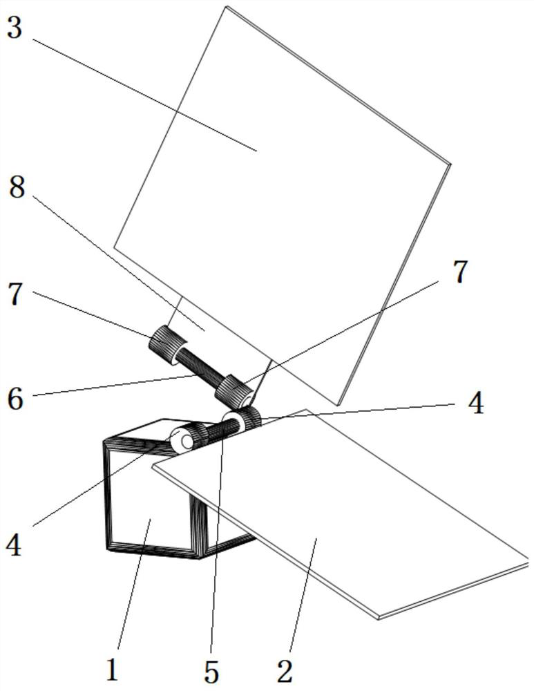
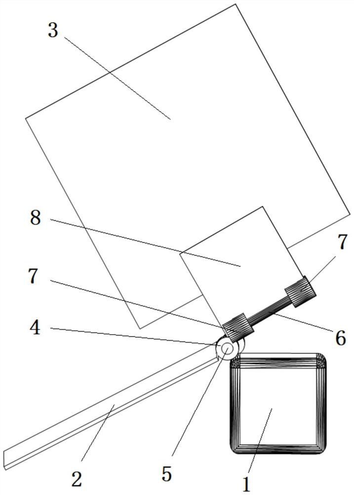
[0022] Such as figure 1 with 2 As shown, the mooring anchor chain observation tooling includes a magnetic suction device 1, a viewing mirror 2, and an observation mirror 3. The magnetic suction device 1 is welded and fixed with two first nuts 4, and the two first nuts 4 are threadedly connected. The first bolt 5, the viewfinder mirror surface 2 is fixed with the first bolt 5 and can rotate with the first bolt 5, the first nut 4 is fixedly connected with the second bolt 6, and the end of the second bolt 6 is connected with the first bolt 5. The first nut 4 is fixedly connected, the second bolt 6 is threaded with two second nuts 7, the observation mirror 3 is fixed with the second nut 7 and can rotate with the second nut 7, the The included angle between the viewing mirror 2 and the viewing mirror 3 is an acute angle, and the upper surface of the viewing mirror 2 is used for framing and reflecting to the front surface of the viewing mirror 3 . The included angle between the se...

Embodiment 2

[0027] On the basis of Embodiment 1, the second bolt 6 and the first nut 4 are fixedly connected through a universal adjustment mechanism (not shown in the figure), and the universal adjustment mechanism is a conventional structure in the field of mechanical structures, which can It is enough to realize universal adjustment and fixation, such as universal ball head structure, etc., by setting a universal adjustment mechanism, the observation mirror surface 3 is not limited to rotate with the second bolt 6 to adjust its angle relative to the viewfinder mirror surface 2, and can also make The observation mirror 3 is rotated and adjusted within the rotation range of the universal adjustment mechanism, which increases the adjustment range of the observation mirror 3 relative to the viewfinder mirror 2, makes the adjustment range more diverse, and is more conducive to correct and rapid adjustment of the observation mirror 3 and the viewfinder mirror 2 The relative angle between them...

Embodiment 3

[0029] On the basis of embodiment 1 or embodiment 2, lock nuts (not shown) are threaded on the first bolt 5 and the second bolt 6, when the viewfinder mirror 2 and the observation mirror 3 are adjusted , the lock nut can be rotated, so that the lock nut tightens the corresponding first nut 4 and the second nut 7, avoiding accidental rotation of the viewfinder mirror 2 and the observation mirror 3, ensuring the stability of the structure, and making the observation process go smoothly.


PUM


Abstract

The disclosure relates to anchor chain observation tooling, including a magnetic suction device, a viewing mirror, and an observation mirror. The magnetic suction device is welded and fixed with two first nuts, and the two first nuts are threadedly connected with a first bolt. The viewing mirror is connected to the first bolt. It is fixed and can rotate with the first bolt. The first nut is fixedly connected with the second bolt, and the second bolt is threaded with two second nuts. The observation mirror is fixed with the second nut and can rotate with the second nut. The viewfinder mirror is connected with the second nut. The included angle of the viewing mirror is an acute angle, and the upper surface of the viewing mirror is used for framing and reflecting to the front surface of the viewing mirror. The structure is simple and the cost is low. It is applied to the anchoring site of the ship to observe the state of the anchor chain continuously and effectively, without scratching the hull structure, ensuring the safety of the structure, and at the same time ensuring the safety of the anchoring personnel.

Description

technical field [0001] The present disclosure relates to the technical field of ships, and in particular to anchor chain observation tooling. Background technique [0002] Anchoring is required in both the sailing test in the ship field and the operation and use stage of the ship. The choice of anchorage needs to refer to the water flow and wind direction, and it is necessary to continuously observe the state, orientation, angle, etc. of the anchor chain to judge the relative displacement and state between the ship and the anchor point. If the observation is neglected, the anchor chain often scratches the ball For hull structures such as the nose and bow, the angle of the anchor chain may even be too large to make it impossible to retract the anchor chain. In the traditional observation method, the anchorman usually adopts the observation method at the position of the bulwark on the side of the ship, and observes frequently for many times, and the anchorman observer has the...

Claims


Application Information

Patent Timeline
Patent Type & Authority Patents(China)
IPC IPC(8): G02B23/02G02B23/16G02B7/198B63B21/00G02B7/182
CPCG02B23/02G02B23/16G02B7/1821B63B21/00B63B2021/003
Inventor 黄翔宇涂文晏关汝滔蔡嘉丽郑金明俞叶舟
Owner CSSC HUANGPU WENCHONG SHIPBUILDING COMPANY
Why Eureka
Try Eureka