Household water supply and drainage control and voltage type water level display

A voltage type, display technology, used in liquid level control, non-electric variable control, control/regulation systems, etc., can solve problems such as lack of versatility, and achieve the effect of low line loss and long transmission distance

Inactive Publication Date: 2020-07-17
骆金山
View PDF0 Cites 0 Cited by
  • Summary
  • Abstract
  • Description
  • Claims
  • Application Information

AI Technical Summary

Problems solved by technology

[0003] Its biggest disadvantage is the lack of versatility. The upper and lower water level differences are fixed, and the controllers with different water level differences must be selected for water tanks of different heights.

Method used


Image

  • Household water supply and drainage control and voltage type water level display
  • Household water supply and drainage control and voltage type water level display
  • Household water supply and drainage control and voltage type water level display

Examples


Embodiment Construction

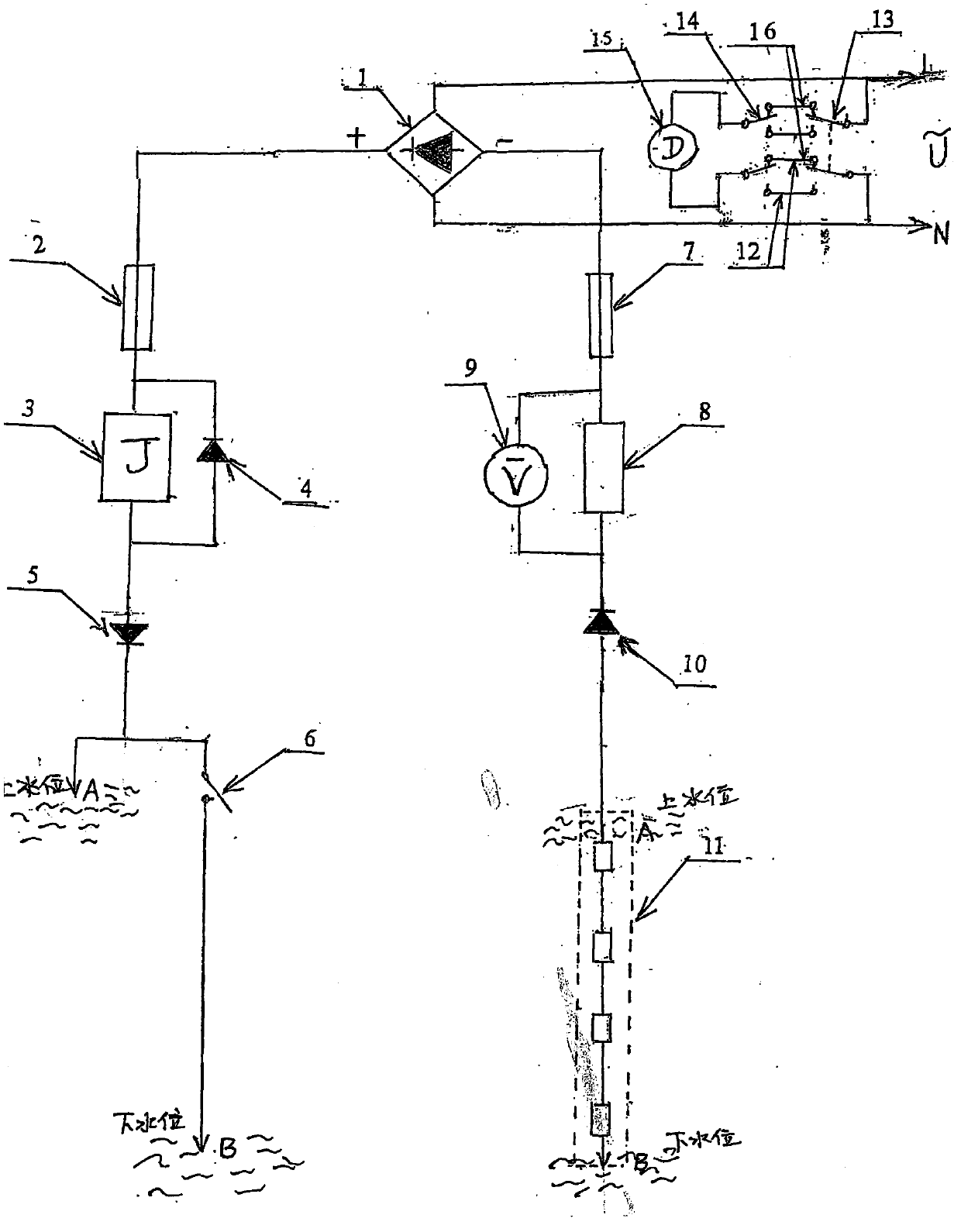
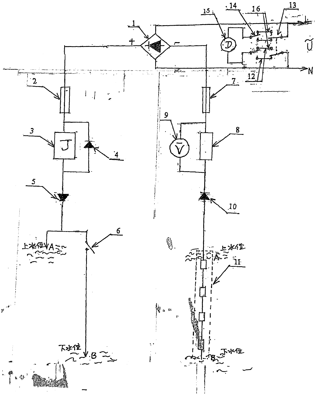
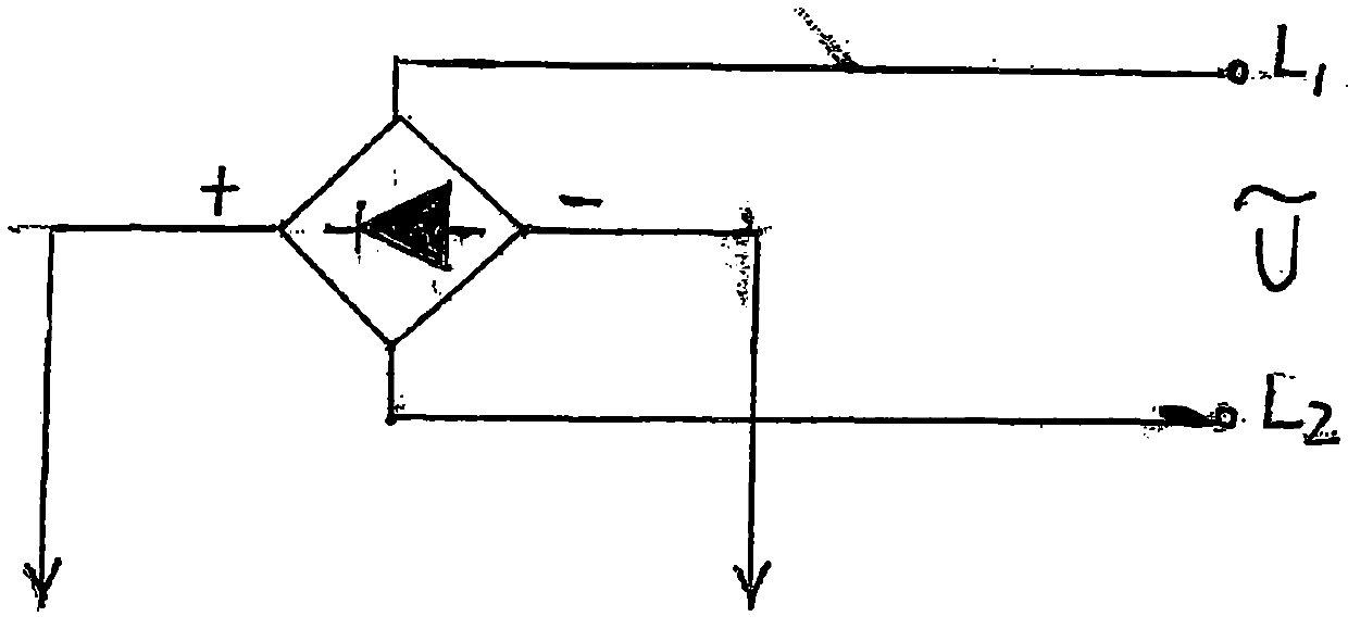
[0032] figure 1 It is an electrical schematic diagram of one embodiment of household water supply and drainage control and voltage type water level display. The DC negative pole output by the AC power supply through the rectifier bridge (1) is sequentially connected in series with the negative pole of the fuse (2), the relay coil (3), and the grounding second connection (5), and the positive terminal of the grounding connection (9) is set at the upper limit of the water level. At the point (A), the positive electrode of the grounding two connection pipe (5) is connected in series with the normally open contact (6) of the relay to set the end point at the lower limit point (B) of the water level. The freewheeling tube (4) is connected in parallel to both ends of the relay coil (3).

[0033] The two ends of the water pump motor (15) are respectively connected to the two changeover contacts (14) of the relay, and the two normally closed contacts (16) of the relay are connected ...


PUM


Abstract

According to the household water supply and drainage control and voltage type water level display, a bridge rectifier cathode is connected with a safety wire, a relay coil and a diode cathode in series; a circuit is led out from the diode anode to be connected with an upper water level point A, and another circuit is led out from the diode anode to be connected with a lower limit water level pointB after being connected with a relay normally-open contact. The power supply is connected to the input end of the change-over switch, the output end of the change-over switch is switched between a relay normally-closed contact and a relay normally-open contact, and a relay switching contact is connected with the motor. The bridge rectifier anode is connected in series with a fuse, a current-limiting resistor, a diode and a water level resistor series group. The voltmeter is connected in parallel with the current-limiting resistor to indicate the water level. When the water level reaches the point A, current is generated between water and the bridge rectifier cathode, the relay is closed, the normally-closed contact is disconnected, and the water pump stops rotating. When the water level reaches the point B, the relay coil has no current, the relay is released, the normally-closed contact is closed, and the water pump supplies water. The power supply is connected to the relay normallyopen contact via the change over switch; when the water is high, the water pump drains water, and when the water is low, the water pump stops running. Conversion of water supply and drainage can be realized.

Description

technical field [0001] The invention belongs to the field of electric appliances. Background technique [0002] The existing technology of using floating magnets to trigger the closing (or opening) of the reed switch contacts to control the water level, because the current capacity that the reed switch contacts can control is small, it must be equipped with an amplifying power system; and it has no water level Display function. [0003] Its bigger shortcoming is lack of versatility, and its upper and lower water level difference is fixed, and the water tank of different height must select the controller of different water level difference. Contents of the invention [0004] A household water supply and drainage control and voltage-type water level display, including a rectifier bridge (1), a fuse (2), a relay coil (3), a freewheel tube (4), a grounding diode (5), and a relay normally open contact (6), fuse (7), current-limiting resistor (8), DC voltmeter (9), grounding d...

Claims


Application Information

Patent Timeline
IPC IPC(8): G05D9/12H02M7/06H02M1/32
CPCG05D9/12H02M1/32H02M7/06
Inventor 骆金山
Owner 骆金山
Why Eureka
Try Eureka