
Rapid design method of traveling-wave tube periodic permanent magnet focusing system

A technology of periodic permanent magnet focusing and design method, applied in the direction of design optimization/simulation, CAD numerical modeling, etc., can solve the problems of magnetic steel performance change, magnetic steel scrap, and time-consuming

Active Publication Date: 2020-07-17
UNIV OF ELECTRONICS SCI & TECH OF CHINA
View PDF7 Cites 6 Cited by
  • Summary
  • Abstract
  • Description
  • Claims
  • Application Information

AI Technical Summary

Problems solved by technology

[0003] The actual magnetic system design and manufacture process is cumbersome and time-consuming
And there are many uncertainties in this process, including: repeated charging and demagnetization will change the performance of the magnetic steel, and even make the magnetic steel scrapped; when measuring the magnetic field, the human operation is not fine or the error of the measuring instrument itself may cause the magnetic field measurement. The deviation between the value and the actual value is too large; during the debugging process of the upper tube, due to the misalignment of the assembly or the large deviation between the magnetic system itself and the design value, the performance of the whole tube will be low; in order to correct the electronic injection, the technician will rely on experience A lot of broken magnetic blocks are pasted around the magnetic steel, but doing so will cause a big difference between the actual magnetic field distribution and the magnetic field distribution required by the design
[0004] When the electric vacuum device develops towards the high-frequency millimeter wave or even terahertz, the size of the magnetic system is smaller, the electron beam is thinner, and the allowable error range is smaller. The impact of the above uncertainties on the electron beam is more difficult to estimate.

Method used


Image

  • Rapid design method of traveling-wave tube periodic permanent magnet focusing system
  • Rapid design method of traveling-wave tube periodic permanent magnet focusing system
  • Rapid design method of traveling-wave tube periodic permanent magnet focusing system

Examples


Embodiment Construction

[0022] The technical solutions of the present invention will be described in detail below in conjunction with the accompanying drawings and embodiments.

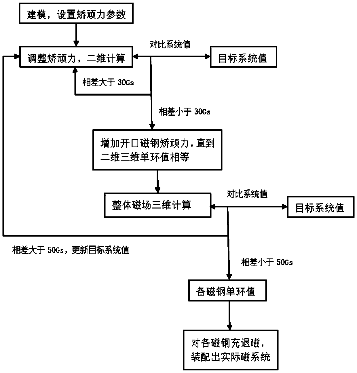
[0023] In this embodiment, for an actual traveling wave tube, the target system value of the magnetic field is obtained according to the electron gun, injection wave interaction and design results of the collector module. The rapid design method of the magnetic system obtains the single ring value of each magnetic steel, and the magnetic field distribution of the actual magnetic system matched according to the single ring value is consistent with the target system value.

[0024] (1) Establish a magnetic system model and a single magnetic ring model, such as figure 2 As shown, the magnetic system consists of 51 pieces of magnetic steel, 50 pieces of pole shoes and magnetic screens at both ends. Set the coercive force of each magnet material as a variable.

[0025] (2) Use MFS for simulation, adjust 51 coercivity parameter...


PUM


Abstract

The invention belongs to the field of traveling wave tube magnetic focusing system design, and particularly relates to a rapid design method of a traveling wave tube periodic permanent magnet focusingsystem. According to target system value distribution, a parameterization mode is used for adjusting a magnetic system: firstly, two-dimensional calculation adjustment is used for obtaining magneticfield distribution conforming to a target system value; adjusting the open magnetic steel to enable the magnetic field distribution obtained by overall three-dimensional calculation to accord with a target system value; obtaining a single-loop value of each piece of magnetic steel according to the material parameters; and finally, a technician can quickly process proper magnetic steel according tothe single-loop value of each piece of magnetic steel.

Description

technical field [0001] The invention belongs to the field of magnetic focusing system design of traveling wave tubes, and specifically relates to a rapid design method of a traveling wave tube periodic permanent magnet focusing system. Background technique [0002] The periodic permanent magnet focusing system is an important part of the traveling wave tube, which affects the emission, focusing and collection of the electron beam. An excellent magnetic focusing system can ensure the laminar flow of the electron beam, suppress dynamic defocus, and keep the electron beam in good condition when it enters the collector. Its design directly affects the performance of the whole tube. [0003] The actual magnetic system design and manufacture process is cumbersome and time-consuming. And there are many uncertainties in this process, including: repeated charging and demagnetization will change the performance of the magnetic steel, and even make the magnetic steel scrapped; when me...

Claims


Application Information

Patent Timeline
Patent Type & Authority Applications(China)
IPC IPC(8): G06F30/20G06F111/10
Inventor 胡权朱世龙胡玉禄朱小芳杨中海李斌
Owner UNIV OF ELECTRONICS SCI & TECH OF CHINA
Learn More