Supercharge Your Innovation With Domain-Expert AI Agents!

Door state detection circuit of access control system

An access control system and detection circuit technology, which is applied in the security field, can solve problems such as static detection schemes and inability to meet the needs of remote door state control, and achieve the effect of accurate state information

Pending Publication Date: 2020-07-17
成都启麦艾科技有限责任公司
View PDF0 Cites 0 Cited by
  • Summary
  • Abstract
  • Description
  • Claims
  • Application Information

AI Technical Summary

Problems solved by technology

[0003] The usual door detection system is composed of a single door magnetic element. Although it can meet certain state detection, its detection scheme is static and cannot meet the needs of modern remote door state control.

Method used


Image

  • Door state detection circuit of access control system
  • Door state detection circuit of access control system

Examples


Embodiment 1

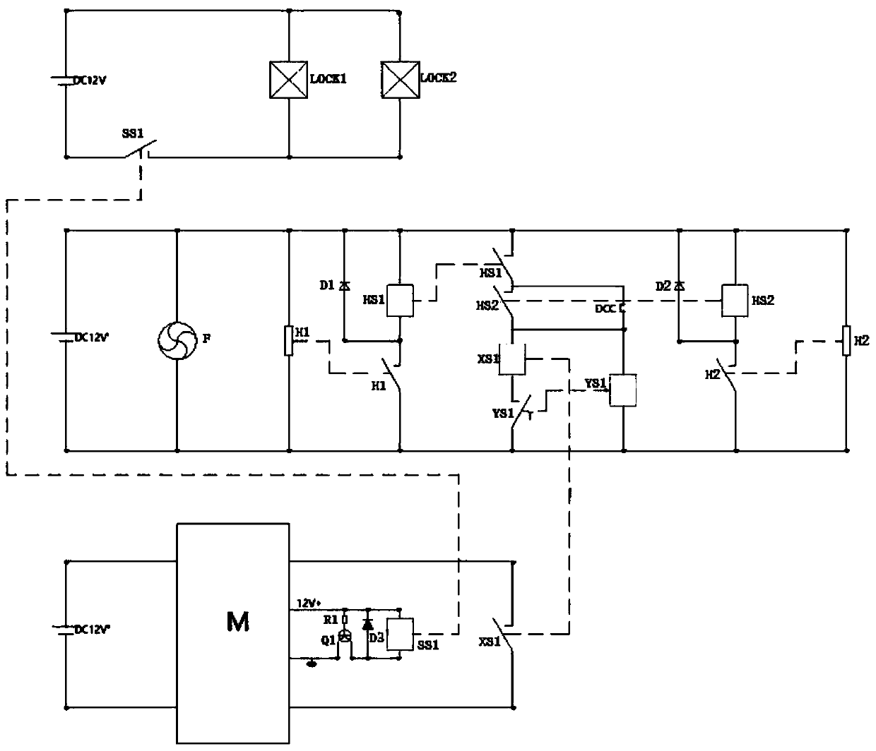
[0028] A door state detection circuit of an access control system mainly detects the state of access control in which two doors are cooperatively closed. Therefore, each door is corresponding to detection elements, which are respectively detection element H1 and detection element H2. The detection element H1 and the detection element H2 are used to signal that the door is closed. The detection element H1 and the detection element H2 are Hall elements. Hall elements are used to detect this action of the door being pushed open.

[0029] The door state detection system includes the above-mentioned detection element H1 and detection element H2. The door locks are door lock LOCK1 and door lock LOCK2 respectively.

[0030] The power supply DC1 is connected to the positive and negative poles of the door lock LOCK1 and the door lock LOCK2, and the power supply DC is provided with a contact of the relay SS1 on the connection line with the door lock LOCK1 and the door lock LOCK2. It ...

Embodiment 2

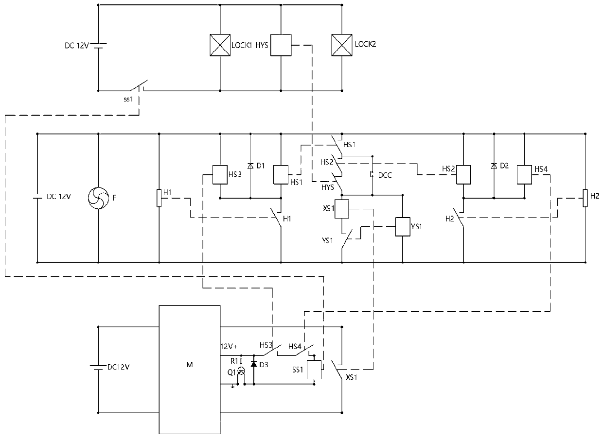
[0043] The difference between this embodiment and Embodiment 1 is that, in order to make this access control detection system also adaptable to the use of a single door leaf, therefore, this embodiment adds a cut-off terminal DCC on the basis of the above-mentioned embodiment 1. This cut-off terminal DCC can be realized with switching elements.

[0044] Specifically, the cut-off terminal DCC is arranged between the other end of the contact of the relay HS1 and the other end of the contact of the relay HS2.

[0045] When there are two doors, the cut-off end is disconnected, and the principle is used as described in embodiment 1 at this moment.

[0046] When there is only one door, the cut-off end is closed. Specifically, for example, when there is only one door, the detection element H2 cannot detect the signal. At this time, the relay HS2 coil is not charged, and the relay HS2 contact is not closed. At this time, due to The cut-off end DCC is turned on, therefore, the other e...

Embodiment 3

[0048] The difference between this embodiment and Embodiment 1 and Embodiment 2 is that the types of door locks targeted by Embodiment 1 and Embodiment 2 are that after pressing the switch and unlocking the door, the door must be pushed open, and the door will return after the push action. position, the door will lock itself.

[0049] In this embodiment, the door lock is an existing new type of automatic door lock, that is, after the door lock is opened, even if there is no action of pushing the door, the door lock will automatically lock again after a certain period of time. Therefore, in this embodiment, adding The delay relay HYS. The two ends of the coil of the delay relay HYS are connected to the positive and negative ends of the above-mentioned power supply DC1, that is, the coil of the delay relay HYS is connected in parallel with the door lock LOCK1 and the door lock LOCK2.

[0050] Further, in this embodiment, the contacts of the delay relay HYS are connected between...


PUM


Abstract

The invention discloses a door state detection circuit of an access control system, which comprises a detection element H used for detecting the state of a door. The door lock is powered by a power supply, and a contact of a relay SS1 is arranged between the door lock and the power supply; a coil of the relay SS1 is communicated with a host M, and the host M controls whether the coil of the relaySS1 is electrified or not; the signal receiving end of the host M is further connected with a contact of a relay XS1 to control whether a process state signal that the door is opened before being closed is sent to the host M or not; a contact of the detection element H controls whether a coil of the relay HS is conducted or not; a contact of the relay HS controls whether a coil of the relay YS1 isconducted or not; a contact of the relay HS2 and a contact of the relay YS1 control whether the relay coil XS1 is conducted or not; the relay YS1 is a time-delay relay, and a contact of the relay YS1is a normally-closed contact; and the rest relay contacts are normally open contacts.

Description

technical field [0001] The invention relates to the field of security technology, in particular to a door state detection circuit of an access control system. Background technique [0002] With the development of the economy and the progress of the society, the development of security equipment has become one of the indispensable items for building a safe and harmonious community. Among them, in the access control system, the detection requirements for the state of the door are getting higher and higher, because the detection of the state of the door directly affects the judgment of the system information of the Internet of Things system, so a comprehensive door state detection system has become a must in the access control system of the Internet of Things. Indispensable important link. [0003] The usual door detection system is composed of a single door magnetic element. Although it can meet certain state detection, its detection scheme is static and cannot meet the requi...

Claims


Application Information

Patent Timeline
Patent Type & Authority Applications(China)
IPC IPC(8): G07C9/00
CPCG07C9/00
Inventor 胡渊
Owner 成都启麦艾科技有限责任公司
Features
  • R&D
  • Intellectual Property
  • Life Sciences
  • Materials
  • Tech Scout
  • Unparalleled Data Quality
  • Higher Quality Content
  • 60% Fewer Hallucinations
Learn More