
Voltage differential sampling circuit and control circuit of switching converter

A technology of switching converters and sampling circuits, which can be used in the measurement of electrical variables, current/voltage, instruments, etc., and can solve the problems of affecting loop control, poor accuracy, and limited stability.

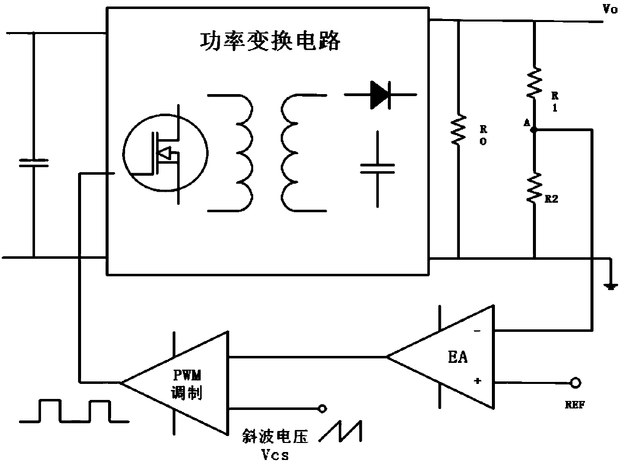
Pending Publication Date: 2020-07-17
SOUTHEAST UNIV +1
View PDF3 Cites 2 Cited by
  • Summary
  • Abstract
  • Description
  • Claims
  • Application Information

AI Technical Summary

Problems solved by technology

However, the stability of this approach is very limited, the accuracy is poor, and it is easy to affect the loop control.

Method used


Image

  • Voltage differential sampling circuit and control circuit of switching converter
  • Voltage differential sampling circuit and control circuit of switching converter
  • Voltage differential sampling circuit and control circuit of switching converter

Examples


Embodiment Construction

[0023] In order to facilitate the understanding of the present invention, the present invention will be described more fully below with reference to the associated drawings. A preferred embodiment of the invention is shown in the drawings. However, the present invention can be embodied in many different forms and is not limited to the embodiments described herein. Rather, these embodiments are provided so that the disclosure of the present invention will be thorough and complete.

[0024] Unless otherwise defined, all technical and scientific terms used herein have the same meaning as commonly understood by one of ordinary skill in the technical field of the invention. The terms used herein in the description of the present invention are for the purpose of describing specific embodiments only, and are not intended to limit the present invention. As used herein, the term "and / or" includes any and all combinations of one or more of the associated listed items.

[0025] It wil...


PUM


Abstract

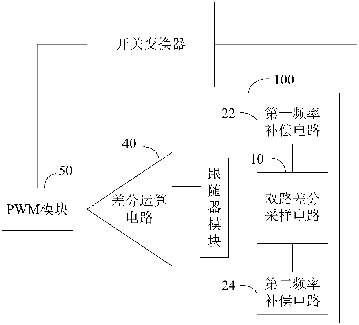
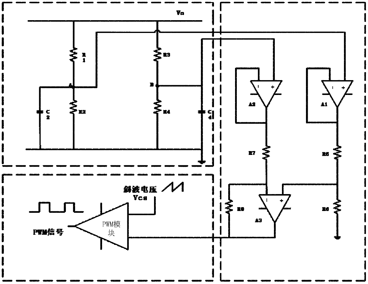
The invention relates to a voltage differential sampling circuit and a control circuit of a switching converter. The voltage differential sampling circuit comprises two differential sampling circuits,wherein the input end of the sampling wiring of each circuit is connected with a voltage sampling point so as to carry out the differential sampling on the voltage sampling point; a frequency compensation module which comprises a first frequency compensation circuit and a second frequency compensation circuit, wherein the first frequency compensation circuit is connected with the first sampling wire, the second frequency compensation circuit is connected with the second sampling wire, and the frequency compensation module is used for eliminating the high-frequency oscillation signals in the voltage signals collected by the two sampling wires; a first voltage follower of which the input end is connected with the first sampling wire; a second voltage follower of which the input end is connected with the second sampling wire; and a differential operation circuit which is used for carrying out subtraction operation on the voltage signals outputted by the two voltage followers and then outputting an operation result. According to the present invention, the frequency compensation module is arranged to attenuate the high-frequency components, the voltage followers are used for bufferingand isolating, and finally the voltage signal with common-mode noise eliminated is obtained.

Description

technical field [0001] The invention relates to voltage sampling, in particular to a voltage differential sampling circuit and a control circuit of a switching converter. Background technique [0002] The sampling circuit is an essential part when the feedback loop is involved in the analog circuit, and it is especially important in the design of the switching power supply. With the rapid development of the power electronics field, high reliability and high power density have become important indicators for measuring switching converters. It is necessary to input the sampled voltage into the error amplifier, and obtain a stable output result through the error signal regulation loop output by the error amplifier. [0003] The commonly used sampling method in switching power supply design is to divide the voltage by two sampling resistors to obtain the sampling voltage. However, the stability of this approach is very limited, the accuracy is poor, and it is easy to affect th...

Claims


Application Information

Patent Timeline
IPC IPC(8): H02M1/00H02M1/12G01R19/00
CPCH02M1/12H02M1/00G01R19/00H02M1/0006H02M1/123
Inventor 钱钦松邵宸晟郭守誉张琥许胜有孙伟锋时龙兴
Owner SOUTHEAST UNIV
Learn More