Roaming control method and device

A technology of roaming control and site, applied in the field of network communication, to achieve the effect of reducing multi-hop transmission of data, good network performance, and suitable control method.

Active Publication Date: 2020-07-17
SHENZHEN GONGJIN ELECTRONICS CO LTD
View PDF4 Cites 2 Cited by
  • Summary
  • Abstract
  • Description
  • Claims
  • Application Information

AI Technical Summary

Problems solved by technology

[0004]The design defect of the above scheme is that only when the STA is far enough away from the currently connected AP, the AP can trigger the roaming control logic, and then the gateway selects a stronger signal AP

Method used


Image

  • Roaming control method and device
  • Roaming control method and device
  • Roaming control method and device

Examples


Embodiment approach

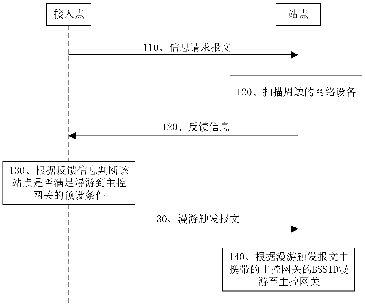
[0038] The access point receives the feedback information sent by the station, and then triggers the roaming control logic. optional, see Figure 4 , a specific implementation of step 130 includes the following steps:

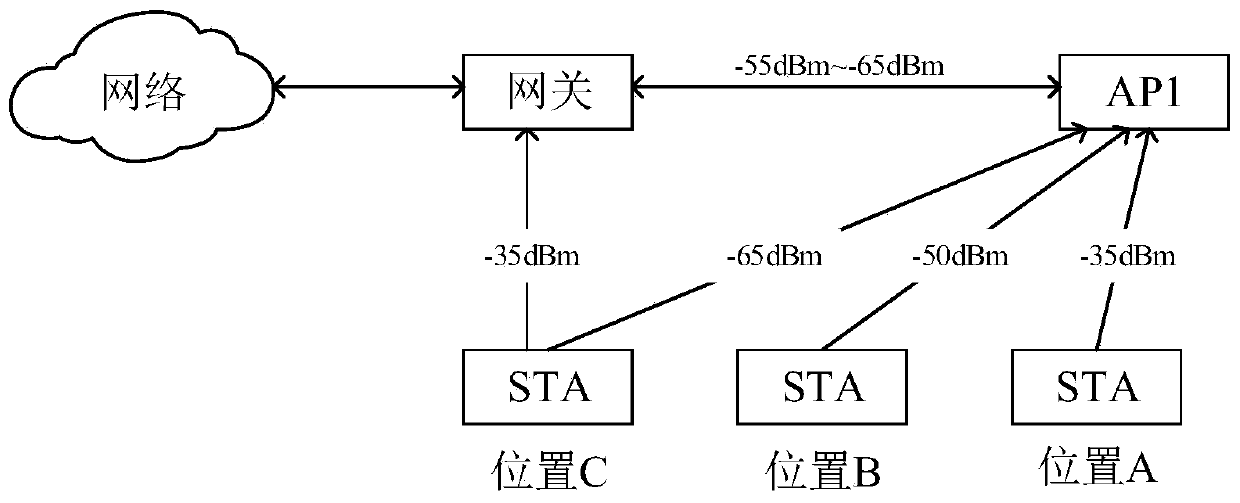
[0039] Step 131: Determine whether the feedback information includes the BSSID of the master control gateway, if yes, go to step 132, if not, go to step 134.

[0040] Step 132: Judging whether the signal strength of the main control gateway at the site in the feedback information is greater than the set threshold, if greater, go to step 133, if not, go to step 134.

[0041] The threshold set here can be set according to empirical values, for example, set to -60dBm.

[0042] Step 133: Determine that the station satisfies the preset condition for roaming to the master control gateway.

[0043] Step 134: Determine that the station does not meet the preset condition for roaming to the master control gateway.

[0044] After it is determined that the station sati...

specific Embodiment approach

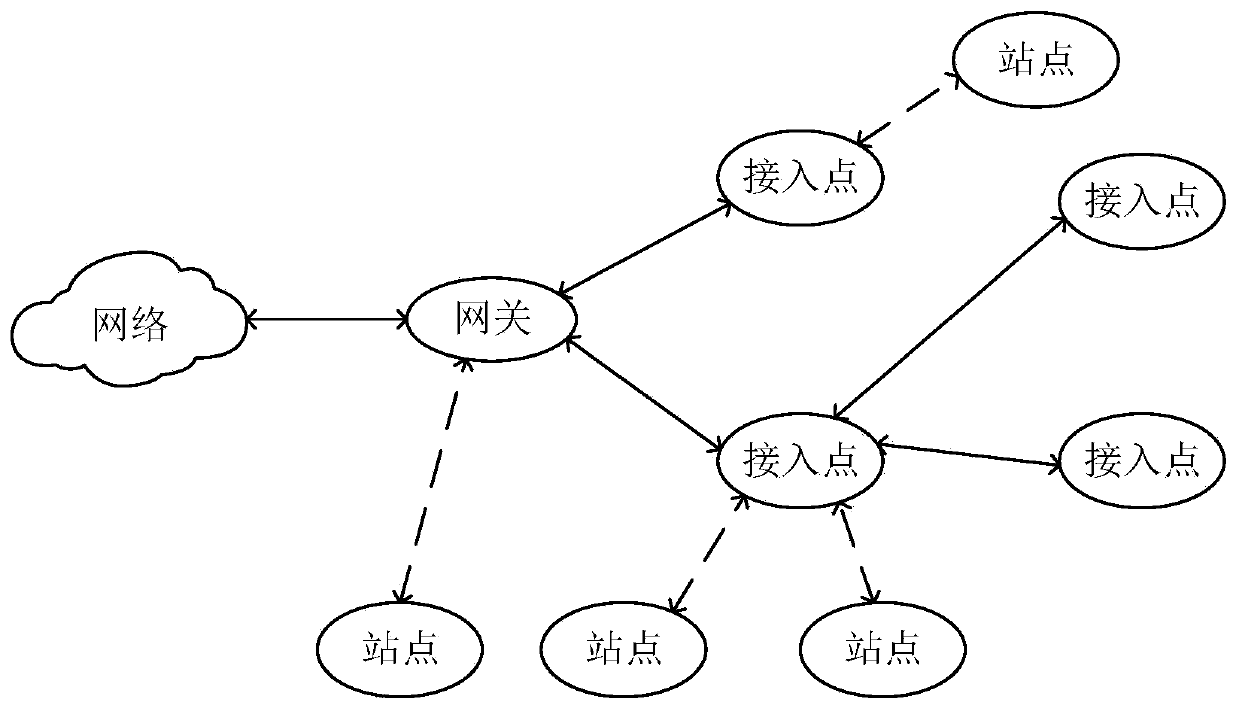
[0048] Next, the embodiment of the present application describes a specific implementation of the roaming control method in detail. This specific implementation mainly describes the execution steps at the access point side, including:

[0049] The first step is to initialize the cycle.


PUM


Abstract

The invention provides a roaming control method and device, and relates to the technical field of network communication. The roaming control method comprises the following steps: sending an information request message to a connected station, wherein the information request message carries an SSID of a mesh network; receiving feedback information sent by the station, wherein the feedback information comprises the BSSID and the signal intensity of the network equipment corresponding to the SSID and scanned by the station; and determining whether the station meets a preset condition of roaming toa main control gateway or not according to the feedback information, and if so, sending a roaming trigger message to the station, the roaming trigger message carrying the BSSID of the main control gateway, and the roaming trigger message being used for instructing the station to roam to the main control gateway. The invention provides a new roaming triggering mechanism, roaming is triggered without depending on signal intensity, and the station is preferentially associated to the gateway of the first hop according to the scanning result of the station, so that the control mode is more reasonable, and the network performance is better for the station.

Description

technical field [0001] The present application relates to the field of network communication technologies, and in particular, to a roaming control method and device. Background technique [0002] Mesh Network (Mesh Network, Mesh Network) has become a hot spot in the field of wireless routers in recent years. Manufacturers of network equipment have begun to introduce a solution that can meet a wide range of wireless coverage, that is, a mesh network is composed of multiple network devices. To eliminate the lack of wireless coverage of a single network device. In this regard, the WiFi Alliance launched the Wi-FiEasyMesh standard, which is an "easy-to-use, self-organizing, intelligent full-coverage Wi-Fi network" composed of multiple wireless access points, which is very suitable for covering large wireless areas network solutions. [0003] However, the EasyMesh standard does not clearly define all the details of triggering roaming between stations and access points, but only...

Claims


Application Information

Patent Timeline
Patent Type & Authority Applications(China)
IPC IPC(8): H04W8/08H04W36/00H04W36/08H04W36/30
CPCH04W8/08H04W36/0083H04W36/30H04W36/08
Inventor 孙戈宇董浩黄双榜
Owner SHENZHEN GONGJIN ELECTRONICS CO LTD
Why Eureka
Try Eureka